
Small-sized disinfected water generator and its usage method

A technology for disinfecting water and generator, applied in the field of electrochemical applications, can solve the problems of failing to provide a sufficiently miniaturized generator, unable to solve the problems of small size, portability, and inability to carry, so as to improve electrolysis efficiency, miniaturized portable use, and operation. handy effect

Inactive Publication Date: 2006-07-19
SHANGHAI SECOND POLYTECHNIC UNIVERSITY
View PDF3 Cites 18 Cited by
  • Summary
  • Abstract
  • Description
  • Claims
  • Application Information

AI Technical Summary

Problems solved by technology

[0004] Most of the strong acidic high potential disinfection water generation devices in foreign countries are large-scale machines, which are directly connected to water pipes and are used in public places such as hospitals. This type of generating device is large in size, high in cost, and inconvenient to install. It is not suitable for small areas such as families. use, not to carry
[0005] Chinese patent CN01246856.8 "Siphon Type High Oxidation Potential Disinfectant Water Generator Adding Electrolyte" discloses that when the water flow changes due to changes in tap water pressure, the amount of NaCl solution added can also be proportionally changed to ensure It ensures the stability of the ORP and pH value of the disinfected water. This is an improved structure of the generating device directly connected to the water pipeline, which cannot solve the problem of small size and portability.
[0009] With the improvement of people's living standards, along with the prevention and treatment of various large-scale epidemic diseases, the demand for miniaturization and portable disinfectant water generators is increasingly urgent, but the above disclosed technologies, methods and devices have not provided enough Generator that is compact and easy to carry when going out

Method used


Image

  • Small-sized disinfected water generator and its usage method
  • Small-sized disinfected water generator and its usage method

Examples


Embodiment Construction

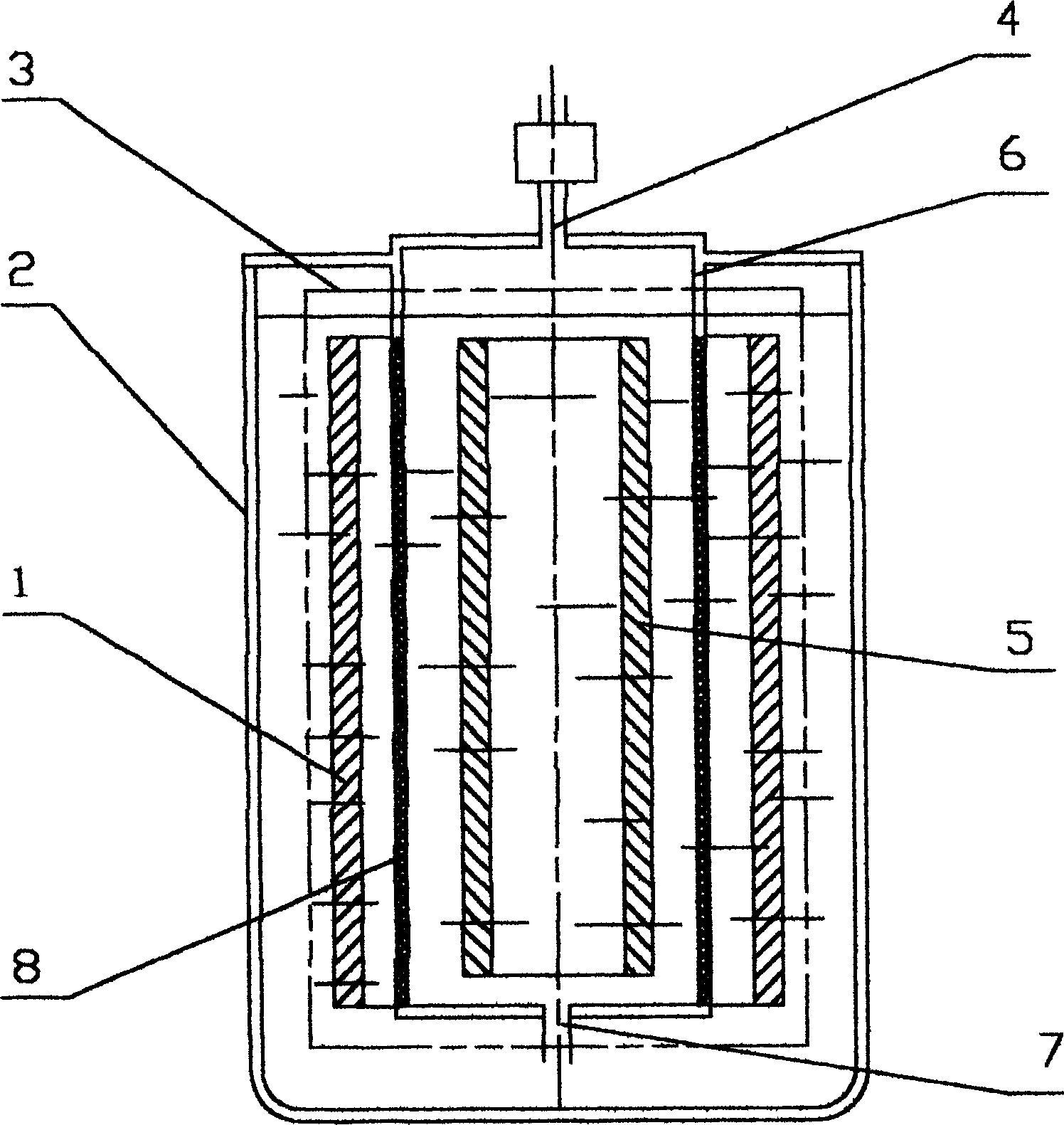
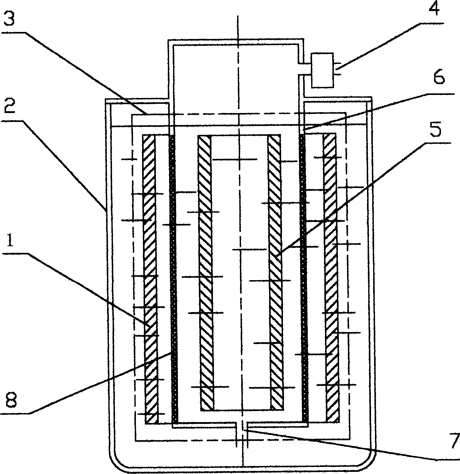
[0022] A small-sized disinfectant water generator of the present invention is in the shape of a cylinder, and is configured by coaxially inserting an inner cylinder body (6) and an outer cylinder body (2).

[0023] The lower part of the inner cylinder (6) is a closed cylinder, and its side surface is composed of an ion exchange membrane (8). The inner surface of the ion exchange membrane (8) is provided with a circular negative electrode (5), and the outer surface is provided with a The ring-shaped positive electrode (1), the top of the inner cylinder (6) offers a hole-shaped airway opening and closing hole (4), and the position of the hole must be higher than the height of the electrolyte level when the electrolysis is working, regardless of It is provided on the upper surface or the side of the upper part of the inner cylinder, and a hole-like electrolyte inlet and outlet (7) is provided on the lower surface of the inner cylinder (6).

[0024] The outer cylinder body (2) is ...


PUM


Abstract

The invention discloses a small-size sanitizer generator and using method in the electrochemical appliance domain, which is characterized by the following: the whole displays column shape; the lateral surface of internal barrel (6) is ionic interchange film (8), which contains negative electrode (5) on the inner side and positive electrode (1) on the outer side; the open and close hole (4) is set on the top of internal barrel (6); the electrolytic solution import-and-export (7) is opened on the lower surface; the external barrel (2) displays longer diameter cylinder than internal barrel (6), whose top can match the internal barrel (6) to insert; the positive and negative electrode and ionic interchange film (8) constitute electrolytic device (3); when the electrolyte is injected in the external barrel (2), the electrolytic device (3) is connected to start electrolytic separation; the power is closed after the sanitizer satisfies the standard; the alkali liquid is discharged from the open and close hole (4) through lifting and moving the internal barrel (6), which forms the sanitizer in the external barrel (2) to finish the working flow path.

Description

(1) Technical field [0001] The invention belongs to the field of electrochemical application technology, and in particular relates to a device for generating a sterilizing and disinfecting solution by using the principle of electrolysis and its use method. (2) Background technology [0002] It is well known that the principle of strong acidic high-potential disinfectant water generation is to use the effect of DC electric field to make directional migration of anions and cations in water, and to use the selective permeability of ion exchange membranes to anions and cations in aqueous solution to selectively pass through anions and block cations. , so that part of the ions migrate through the ion exchange membrane to another part of the water, so that the electrolyte reaches the standard of strong acidic high potential disinfection water. [0003] Add low-concentration salt to tap water to form an electrolytic aqueous solution. After the electrode is specially treated, it is ...

Claims


Application Information

Patent Timeline
Patent Type & Authority Applications(China)
IPC IPC(8): A61L2/06C02F1/461C25B1/00
Inventor 王钧
Owner SHANGHAI SECOND POLYTECHNIC UNIVERSITY
Learn More