
Magnetic levitation device

A magnetic levitation and floating body technology, which is applied to display devices, holding devices using magnetic attraction or thrust, instruments, etc., can solve the problems of difficulty in large-scale, small selection range of floating bodies, and complicated installation, so as to reduce the volume and reduce mutual electromagnetic Effects of interference, simplified structure

Inactive Publication Date: 2006-07-12
NINGBO TIANMING ELECTRONICS
View PDF1 Cites 10 Cited by
  • Summary
  • Abstract
  • Description
  • Claims
  • Application Information

AI Technical Summary

Problems solved by technology

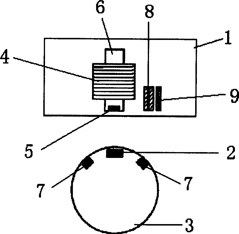
[0005] In order to overcome the disadvantages of the magnetic levitation device in the prior art that the selection range of the floating body is small, the installation is complicated, and it is difficult to enlarge, the present invention provides a magnetic levitation device with a large selection range of the floating body, easy installation, and easy enlargement

Method used


Image

  • Magnetic levitation device
  • Magnetic levitation device
  • Magnetic levitation device

Examples


Embodiment 2

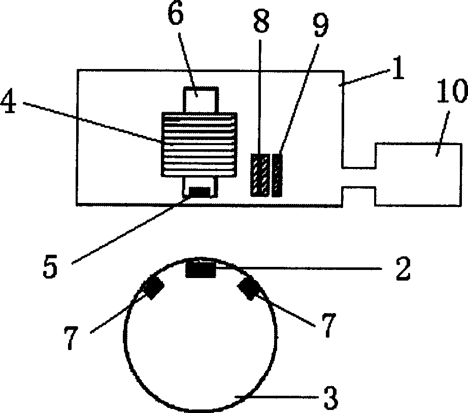
[0024] refer to figure 2 , the magnetic levitation control circuit and the deflection circuit are arranged outside the frame box, the magnetic levitation control circuit and the deflection circuit are all placed in the circuit board box 10, and the magnetic levitation control circuit is connected to the displacement sensor and the electromagnetic The coil of the body, and the deflection circuit connect the rotation sensor and the deflection force generator through wires. The circuit board box 10 is located on the side of the frame box 1 . The external placement of the circuit board can reduce the mutual electromagnetic interference between each magnet and the circuit, and can also reduce the volume of the rack box. The rest of the structure and implementation are the same as in Embodiment 1.

Embodiment 3

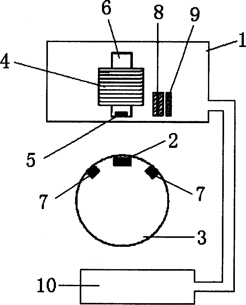
[0026] refer to image 3 , the magnetic levitation control circuit and the deflection circuit are arranged outside the frame box, the magnetic levitation control circuit and the deflection circuit are all placed in the circuit board box 10, and the magnetic levitation control circuit is connected to the displacement sensor and the electromagnetic The coil of the body, and the deflection circuit connect the rotation sensor and the deflection force generator through wires. The circuit board box 10 is located below the floating body 3 . The external placement of the circuit board can reduce the mutual electromagnetic interference between each magnet and the circuit, and can also reduce the volume of the rack box. The rest of the structure and implementation are the same as in Embodiment 1.


PUM


Abstract

The magnetic levitation system comprises: a frame tank with an electromagnet to balance dropping gravity of floating body, a floating body under said tank contained permanent magnet on its c.g.line and a rotation magnet, a displacement sensor to measure floating body position, a magnetic levitation control circuit, and a rotation generation device matched with said rotation magnet; arranging said sensor, control circuit and generation device all in said frame tank. The advantages of this invention include: 1. enlarging selection range for floating body; 2. saving base and frame to simplify structure and benefit to large-scale; and 3. increasing application area.

Description

(1) Technical field [0001] The invention relates to a magnetic levitation device. (2) Background technology [0002] Advertising supplies, teaching supplies, handicrafts, souvenirs, models and many other products are made into magnetic levitation devices with good visual effects. The Chinese utility model patent whose patent number is 99252312.5 just discloses a kind of magnetic levitation device, comprises support, floating body, and the gravity center line of floating body is provided with upper permanent magnet, lower permanent magnet. An electromagnetic box is extended from the upper end of the bracket, and an electromagnet interacting with the upper permanent magnet in the floating body is installed in the electromagnetic box. The lower end of the bracket extends out of the base, and a displacement sensor interacting with the lower permanent magnet in the floating body is installed in the base, and the displacement sensor is connected with the coil signal of the electr...

Claims


Application Information

Patent Timeline
Patent Type & Authority Applications(China)
IPC IPC(8): H02N15/00G09F19/00
Inventor 俞益庭唐建一
Owner NINGBO TIANMING ELECTRONICS
Learn More