Reception device
A receiving device and wireless receiving technology, applied in the direction of electrical components, transmission systems, etc., can solve the problems of small diffusion rate, high power, large number of multipaths, etc., and achieve the effect of circuit scale reduction
- Summary
- Abstract
- Description
- Claims
- Application Information
AI Technical Summary
Problems solved by technology
Method used
Image

Examples
Embodiment approach 1
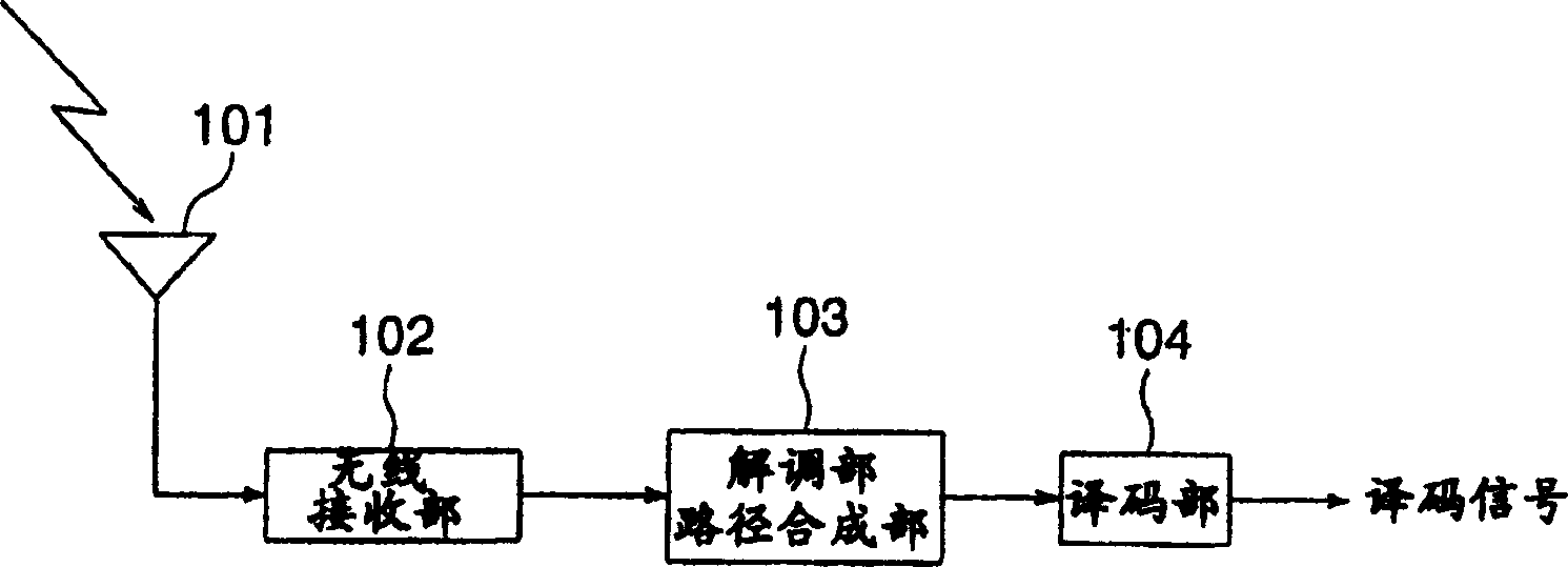
[0023] Embodiment 1 will be described. figure 1 The configuration of Embodiment 1 of the present invention is shown. exist figure 1 In this case, the received signal is received by the receiving antenna 101 , received power amplification, down-conversion, A / D conversion, etc. are performed in the wireless receiving unit 102 , and input to the demodulation unit / path combining unit 103 . In the demodulation unit / path combining unit 103, the despreading process is performed using the spreading code assigned to each mobile station, and the data channel signal extracted after the path combining is output to the decoding unit 104. In the decoding unit 104, the input data channel signal is decoded, and the decoded signal is taken out.
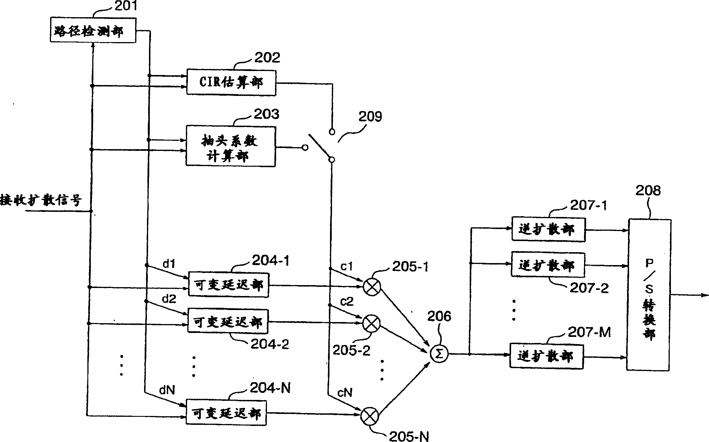
[0024] figure 2 The configuration of the demodulation unit / path synthesis unit 103 is shown. exist figure 2 Among them, the received spread signal is sent to the path detection unit 201, and then input to the CIR (channel impulse response) esti...
Embodiment approach 2
[0042] Embodiment 2 will be described. Figure 4 The structure of the receiver in Embodiment 2 is shown. again, in Figure 4 In , the same reference numerals are assigned to the same parts as those in Embodiment 1, and description thereof will be omitted.
[0043] In this embodiment, after the number of the target paths is determined in the path detection unit 201, tap coefficients corresponding to the number of target paths are obtained in the CIR estimation unit 202 or the tap coefficient calculation unit 203, and these outputs are input to Delay amount / tap coefficient control unit 301 . The delay amount / tap coefficient control unit 301 performs control so that the set delay amount and the number of tap coefficients are determined based on the target path number information, and the operation of the remaining circuits equal to or greater than the target path number is not performed.
[0044] For example, control is performed such that when the number of paths described in...
Embodiment approach 3
[0049] Embodiment 3 will be described. Figure 5 The structure of the receiver in Embodiment 3 is shown. again, in Figure 5 In , the same symbols are assigned to the same parts as those in Embodiment 1 and Embodiment 2, and description thereof will be omitted.
[0050] In this embodiment, the RAM 401 is used instead of the variable delay units 204-1 to 204-N.
[0051] The RAM 401 has a function of delaying the reception spread signal according to each delay amount output from the delay amount / tap coefficient control unit 301 and outputting a signal corresponding to the delay amount.
[0052] The respective outputs of the path detection unit 201, the CIR estimation unit 202, and the tap coefficient calculation unit 203 are input to the delay amount / tap coefficient control unit 301, and are controlled according to the number of target paths.
[0053] According to the delay amount output from the delay amount / tap coefficient control unit 301, output signals corresponding to t...
PUM
 Abstract
Description
Claims
Application Information
 - R&D
- Intellectual Property
- Life Sciences
- Materials
- Tech Scout
- Unparalleled Data Quality
- Higher Quality Content
- 60% Fewer Hallucinations
Browse by: Latest US Patents, China's latest patents, Technical Efficacy Thesaurus, Application Domain, Technology Topic, Popular Technical Reports.
© 2025 PatSnap. All rights reserved.Legal|Privacy policy|Modern Slavery Act Transparency Statement|Sitemap|About US| Contact US: help@patsnap.com