
Super-wide band high-gain printed-gap antenna

A slot antenna and high-gain technology, which is applied in the field of ultra-wideband high-gain printed antennas, can solve problems such as limited gain and narrow bandwidth, and achieve the effects of improved radiation characteristics, easy processing, and exquisite design

Inactive Publication Date: 2006-05-24
HUIZHOU SPEED WIRELESS TECH CO LTD
View PDF0 Cites 9 Cited by
  • Summary
  • Abstract
  • Description
  • Claims
  • Application Information

AI Technical Summary

Problems solved by technology

Due to the limitation of its own structure, this antenna has the disadvantage of narrow bandwidth, and it radiates in two directions, which limits its gain.

Method used


Image

  • Super-wide band high-gain printed-gap antenna
  • Super-wide band high-gain printed-gap antenna
  • Super-wide band high-gain printed-gap antenna

Examples


Embodiment Construction

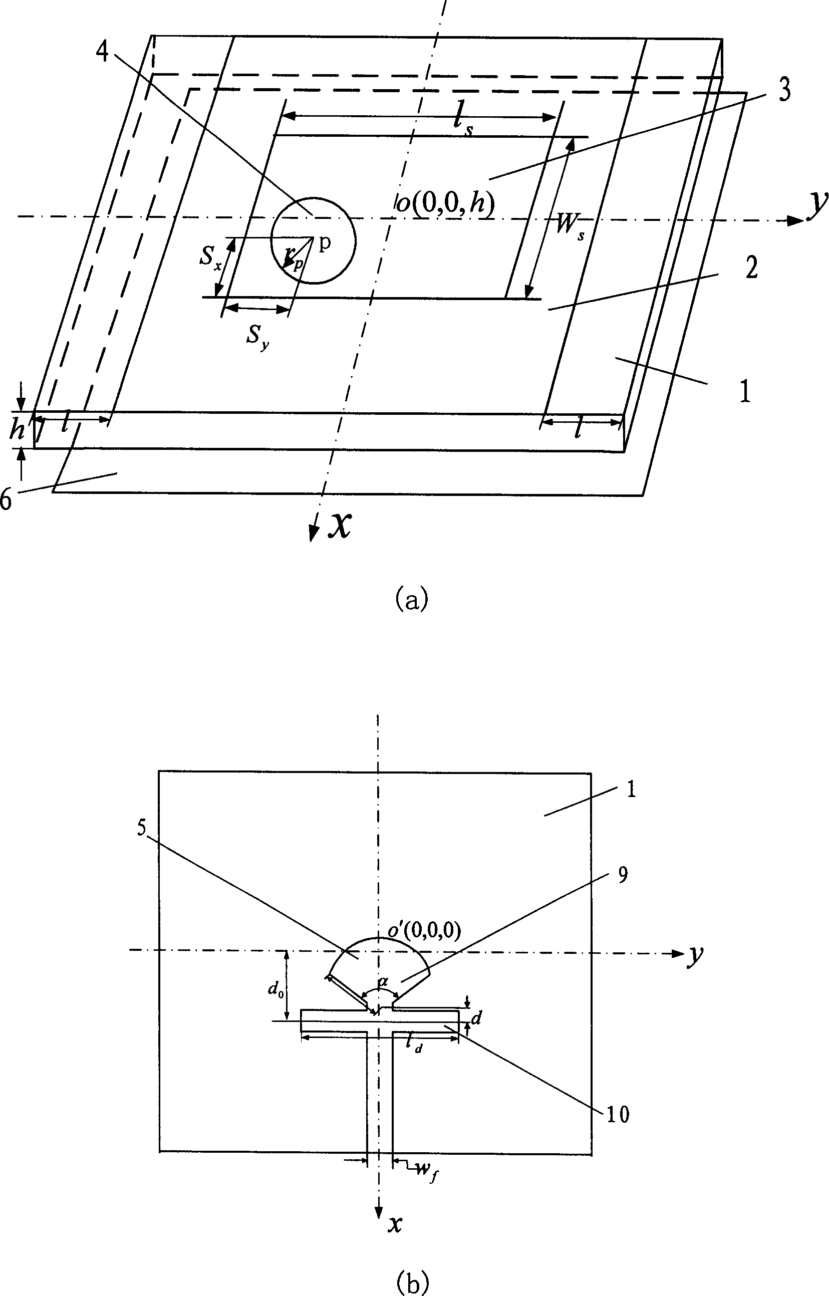
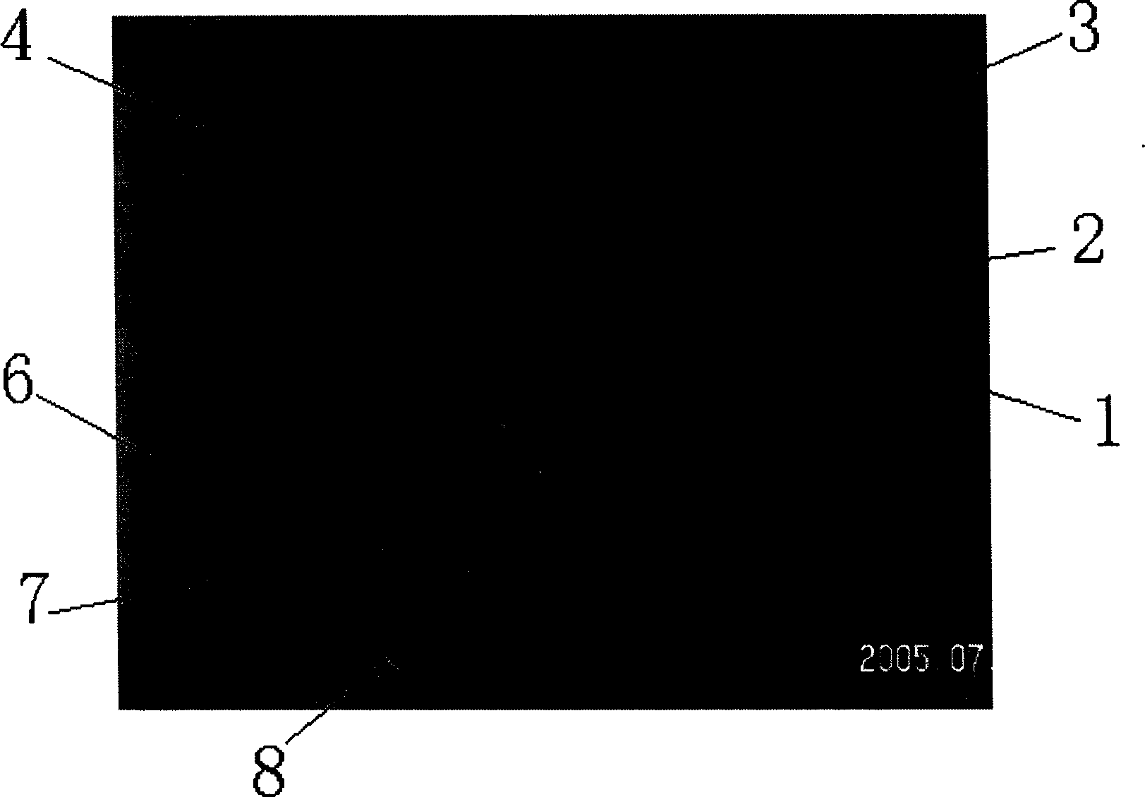
[0029] A preferred embodiment of the present invention: see figure 1 and figure 2 . figure 2 It is a physical map designed and processed according to a certain frequency band. The structure of the antenna is as figure 1 As shown, it consists of a rectangular slit 3 printed on a copper foil ground plate 2 on one side of a dielectric substrate 1, a circular metal patch 4, a microstrip feed source 5 on the other side, and a single-sided copper-clad reflector 6 . The lower end of the microstrip feed 5 is connected to the inner conductor of the coaxial connector 7 , while the outer conductor of the connector is connected to the copper foil ground plate 2 on the other side. (marker 8 among the figure is a one-yuan coin used for size comparison.) The design parameter of the antenna is 1 s 、w s 、r p ,α,r,d,l d And dielectric plate length l, thickness h, relative permittivity ε r . use figure 1structure, as long as the parameters are selected reasonably, the input impedanc...


PUM


Abstract

The antenna consists of rectangle aperture printed on metallic earth plate on a side of medium base plate, circular patch, feed source of microstrip at another side, and metal reflecting plate at back. The wide aperture is as main radiant point. Fan shaped terminal of microstrip feed line connected to horizontal branch node constitutes feed source of microstrip, and circular patch is introduced to obtain super broadband impedance characteristic. The medium base plate is extended properly in order to improve radiation characteristic. Rear additive metal reflecting plate is in use for increasing gain. The antenna can obtain impedance bandwidth more than three frequency octaves (voltage standing wave ratio VSWR less than and equal to 2). Gain can reach to 5.5-8dB in range of bandwidth. Microstrip feed line is adopted in the antenna, and coaxial fitting is connecting piece. Features are: simple planar construction, easy of integration to active circuit, and low cost.

Description

technical field [0001] The invention relates to a printed slot antenna, in particular to an ultra-wideband high-gain printed antenna, which can be used for both receiving and transmitting radio waves. In military terms, it can be used as a terminal antenna for ultra-wideband radio equipment such as electronic reconnaissance and electronic interference, electromagnetic protection and ground penetrating radar. In terms of civil use, it can be used as a base station antenna for short-range ultra-wideband (UWB) communication, and an ultra-wideband antenna for home wireless communication. Background technique [0002] Modern electronic warfare equipment is moving towards the direction of multi-functional integration, small integration, modularization and intelligence. The existing UWB antennas can no longer be combined with advanced high-integration systems due to their complex structures and bulky volumes. It is increasingly important to study miniaturized, high-gain UWB antenn...

Claims


Application Information

Patent Timeline
Patent Type & Authority Applications(China)
IPC IPC(8): H01Q1/38H01Q13/10
Inventor 钟顺时姚凤薇梁仙灵
Owner HUIZHOU SPEED WIRELESS TECH CO LTD
Learn More