
Engine frame

A technology for engine mounts and engines, which can be used in power units, mechanical equipment, springs made of plastic materials, etc., and can solve problems such as lack of rubber elastomers.

Active Publication Date: 2006-03-08
SUMITOMO RIKO CO LTD
View PDF4 Cites 30 Cited by
  • Summary
  • Abstract
  • Description
  • Claims
  • Application Information

AI Technical Summary

Problems solved by technology

However, the designs disclosed in these documents differ from the present invention in that they lack an arrangement in which the upper half of the rubber-elastic body constitutes a stop part in the front-rear direction, and the bridge-shaped metal element does not constitute a stop metal element, The stop metal element works together with the rubber stop part to limit the forward and backward movement

Method used


Image

  • Engine frame
  • Engine frame
  • Engine frame

Examples


Embodiment Construction

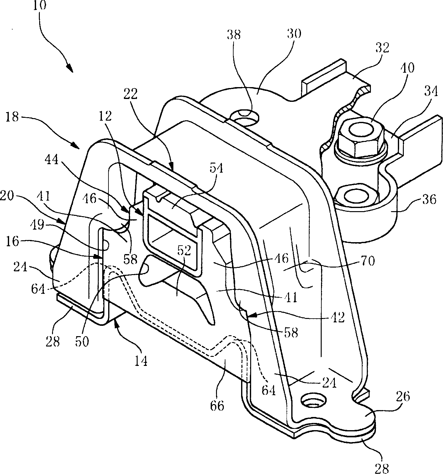
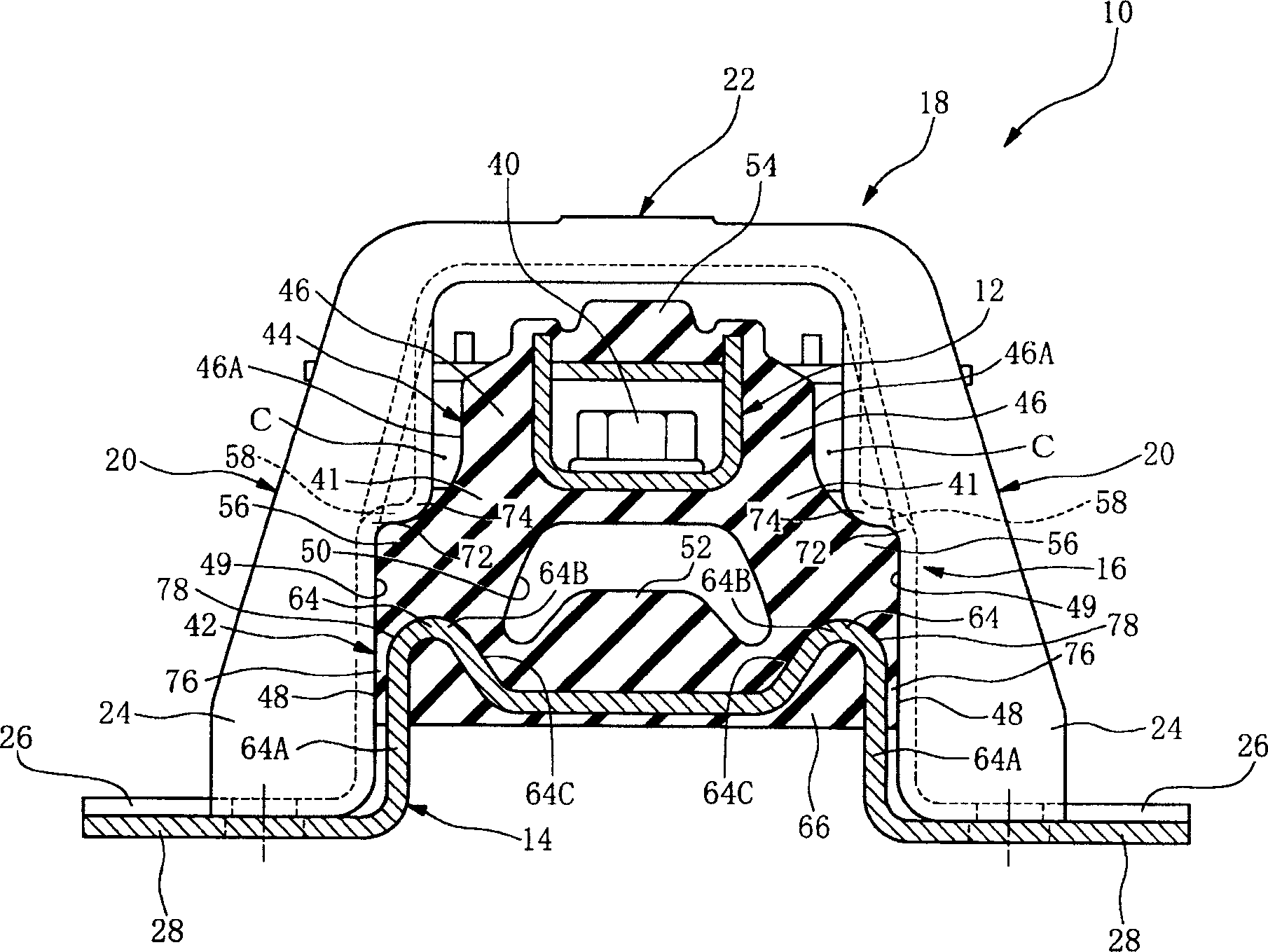
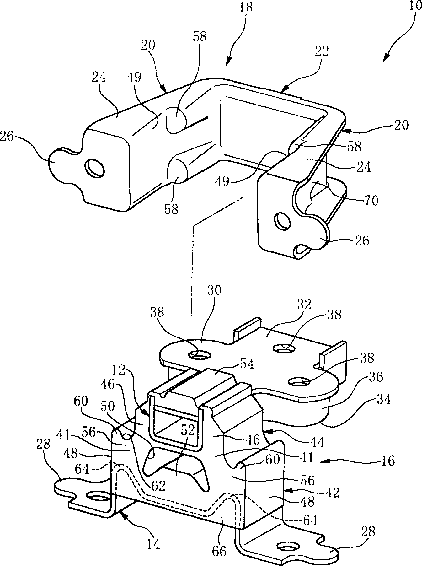
[0050] Embodiments of the invention will be described in detail below with reference to the drawings. exist figure 1 , 3 In and 4, 10 represents an engine mount for a vehicle according to an embodiment, which includes an upper metal element (upper rigid element) 12 fixed on the engine side, and a lower metal element (lower rigid element) 14 fixed on the vehicle body side , a rubber elastic body 16 connecting them together, and a bridge-shaped stop metal member (rigid stop member) 18 constituting a separation from the above-mentioned elements. The rubber elastic body 16 is integrally bonded to the upper and lower metal elements 12, 14 by vulcanization during its vulcanization molding process.

[0051] The bridge-shaped stop metal member 18 has a pair of front and rear strut portions 20 and a bridge portion 22 connecting the pair of strut portions 20 in the vehicle front-rear direction. Such as figure 1 and 3 As shown, the stop metal element 18 is in the left and right di...


PUM


Abstract

An engine mount wherein an elastic body connecting upper and lower rigid members has a front-back dimension of its upper half smaller than that of its lower half with the upper half constitutes a front-back direction rubber stopper portion opposed to and spaced apart from a pair of leg portions of a bridge shaped stopper member in the front-back direction by a stopper clearance. The bridge shaped stopper member is press fitted onto the elastic body and the lower rigid member by being assembled through an opening of a lower end thereof, with the lower half clamped elastically between the pair of leg portions. With the stopper member being press fitted onto the elastic body and the lower rigid member, the pressing portions of the stopper member press downwardly the shoulder portions of the elastic body causing compression deformation of the lower half, producing a state of fixation of the lower half to the stopper member.

Description

[0001] Documents incorporated herein by reference [0002] Japanese Patent Application No. 2004-253081 filed on August 31, 2004, Japanese Patent Application No. 2004-344570 filed on November 29, 2004, and Japanese Patent Application No. 2005-054298 filed on February 28, 2005 were approved Citations are fully incorporated herein, where each document includes specification, figures, and abstract. technical field [0003] The present invention relates to an engine frame supporting a vehicle body engine in a vibration damping manner, and in particular to an engine frame structure, which includes a stopper element which is a bridge-shaped rigid member and adopts a suspension method to provide vibration reduction of the engine support. Background technique [0004] Different types of engine mounts have been used to provide engine damping support. One type consists of a structure which is a metal stop in the form of a bridge (rigid stop) and is suspended to provide vibration-damp...

Claims


Application Information

Patent Timeline
Patent Type & Authority Applications(China)
IPC IPC(8): F16F1/38B60K5/12
Inventor 清水赖重
Owner SUMITOMO RIKO CO LTD
Learn More