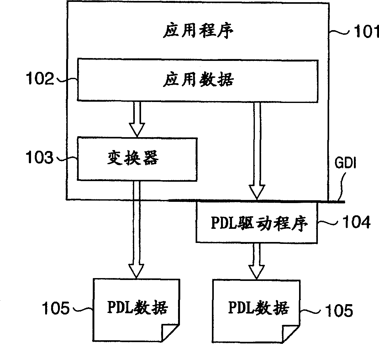
Image processing apparatus and its method
An image processing device and technology combined with the device are applied in the directions of image communication, electrical digital data processing, permanent visual display devices, etc., which can solve problems such as image quality degradation and achieve the effect of preventing image quality degradation.
- Summary
- Abstract
- Description
- Claims
- Application Information
AI Technical Summary
Problems solved by technology
Method used
Image
Examples
Embodiment approach 1
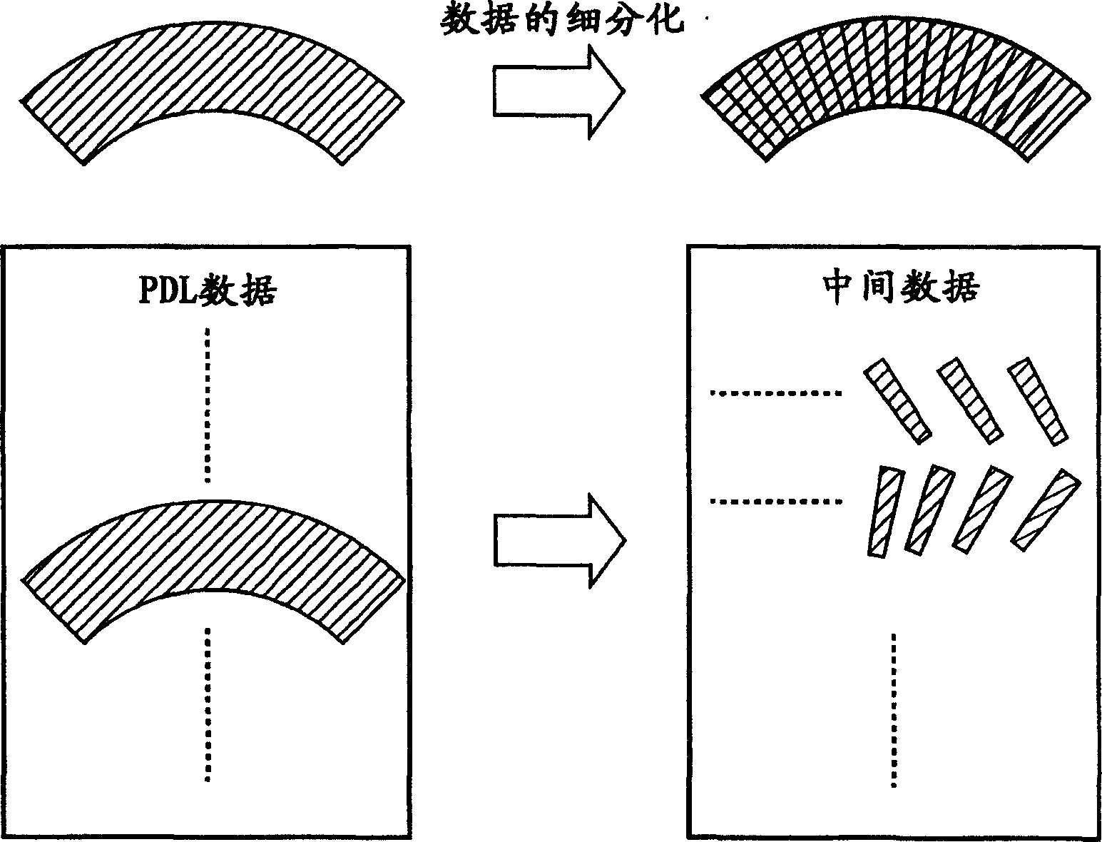
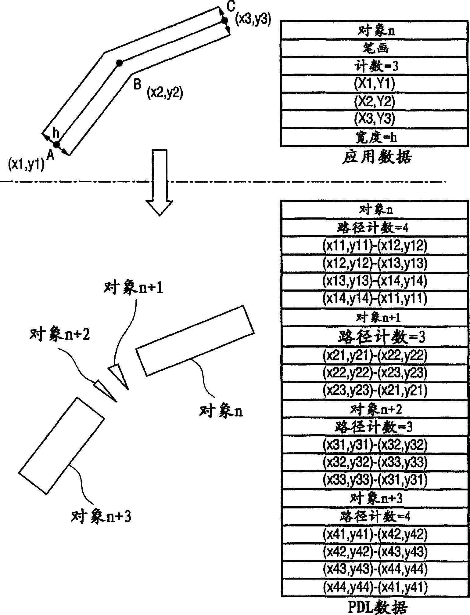
[0041] In order to solve the problem of subdividing the above-mentioned objects, for example, in the state of intermediate data, compare the colors of adjacent objects, if the colors are the same, you can consider adding this kind of processing of combining objects (refer to Figure 24 ). Through this processing, it is possible to avoid deterioration of image quality when trapping is performed on each subdivided object. In this case, since it is necessary to determine the colors of all objects and adjacent objects, the processing time increases. In addition, because the object data is stored in the drawing order in the intermediate data, the color judgment is also in this order, and they are not originally the same object, but even for overlapping objects with the same color, there is a combination process.
[0042] Therefore, it is conceivable to consider a solution in which the metadata indicating the combination of objects is generated in a different way, and the processin...
Embodiment approach 2
[0090] Next, image processing related to Embodiment 2 of the present invention will be described. In addition, in Embodiment 2, the same symbols are attached to the same configuration as in Embodiment 1, and detailed description thereof will be omitted.
[0091] FIG. 14 is a block diagram showing a printing system of Embodiment 2. FIG.
[0092] The cluster server 112 has an interpreter 121 for analyzing PDL data and an intermediate data generation unit 122 for generating intermediate data based on the analysis result. A plurality of print servers 113a, 113b, 113c, . . . , 113n are connected to printers 114a, 114b, 114c, . . . , 114n, respectively. The cluster server 112 distributes the print job to a plurality of print servers 113 and performs print processing using a plurality of printers 114 in consideration of distributing the load of the print job.
[0093] Figure 15 is a diagram showing the flow of print processing including trapping processing. What is important her...
Embodiment approach 3
[0107] The image processing of Embodiment 3 of the present invention will be described below. In addition, in Embodiment 3, the same symbols are assigned to the same configuration as in Embodiments 1 and 2, and detailed description thereof will be omitted.
[0108] FIG. 23 is a flowchart showing the processing of the cluster server 112 of the third embodiment. In Figure 23, for the Figure 21 The same process is given the same symbol, and its detailed description will be omitted.
[0109] In the trapping setting 123 of step S2402, a distributed trapping process can be instructed. That is to say, if the print server 113 can be expected to perform sufficiently high-speed processing, the entire trapping process can also be performed by the print server 113, and if it is possible to set whether to distribute the trapping process in the trap setting 123, it can Provides degrees of freedom to the printing system.
[0110] Therefore, the cluster server 112 determines whether dist...
PUM
 Abstract
Description
Claims
Application Information
 - R&D
- Intellectual Property
- Life Sciences
- Materials
- Tech Scout
- Unparalleled Data Quality
- Higher Quality Content
- 60% Fewer Hallucinations
Browse by: Latest US Patents, China's latest patents, Technical Efficacy Thesaurus, Application Domain, Technology Topic, Popular Technical Reports.
© 2025 PatSnap. All rights reserved.Legal|Privacy policy|Modern Slavery Act Transparency Statement|Sitemap|About US| Contact US: help@patsnap.com


