Insert tube of vacuum circulating degasification apparatus

A technology of vacuum cycle degassing and tube insertion, applied in the direction of improving process efficiency, can solve the problems of small circulating flow and inability to expand inner diameter, and achieve the effect of increasing steel output

Inactive Publication Date: 2006-02-08
SHANXI TAIGANG STAINLESS STEEL CO LTD
View PDF0 Cites 2 Cited by
  • Summary
  • Abstract
  • Description
  • Claims
  • Application Information

AI Technical Summary

Problems solved by technology

Due to the limitation of the distance between the connecting pipes used by the vacuum circulation degassing equipment to set the insertion pipes, the distance between the outer...

Method used


Image

  • Insert tube of vacuum circulating degasification apparatus
  • Insert tube of vacuum circulating degasification apparatus
  • Insert tube of vacuum circulating degasification apparatus

Examples


Embodiment Construction

[0023] The specific implementation of the insertion tube for vacuum circulation degassing equipment of the present invention will be described in detail below in conjunction with the examples and accompanying drawings, but the specific implementation of the insertion tube for vacuum circulation degassing equipment of the present invention is not limited to the following examples.

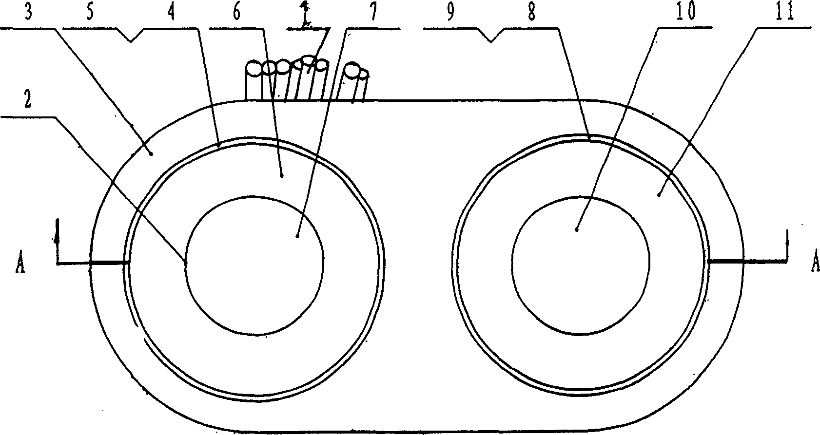
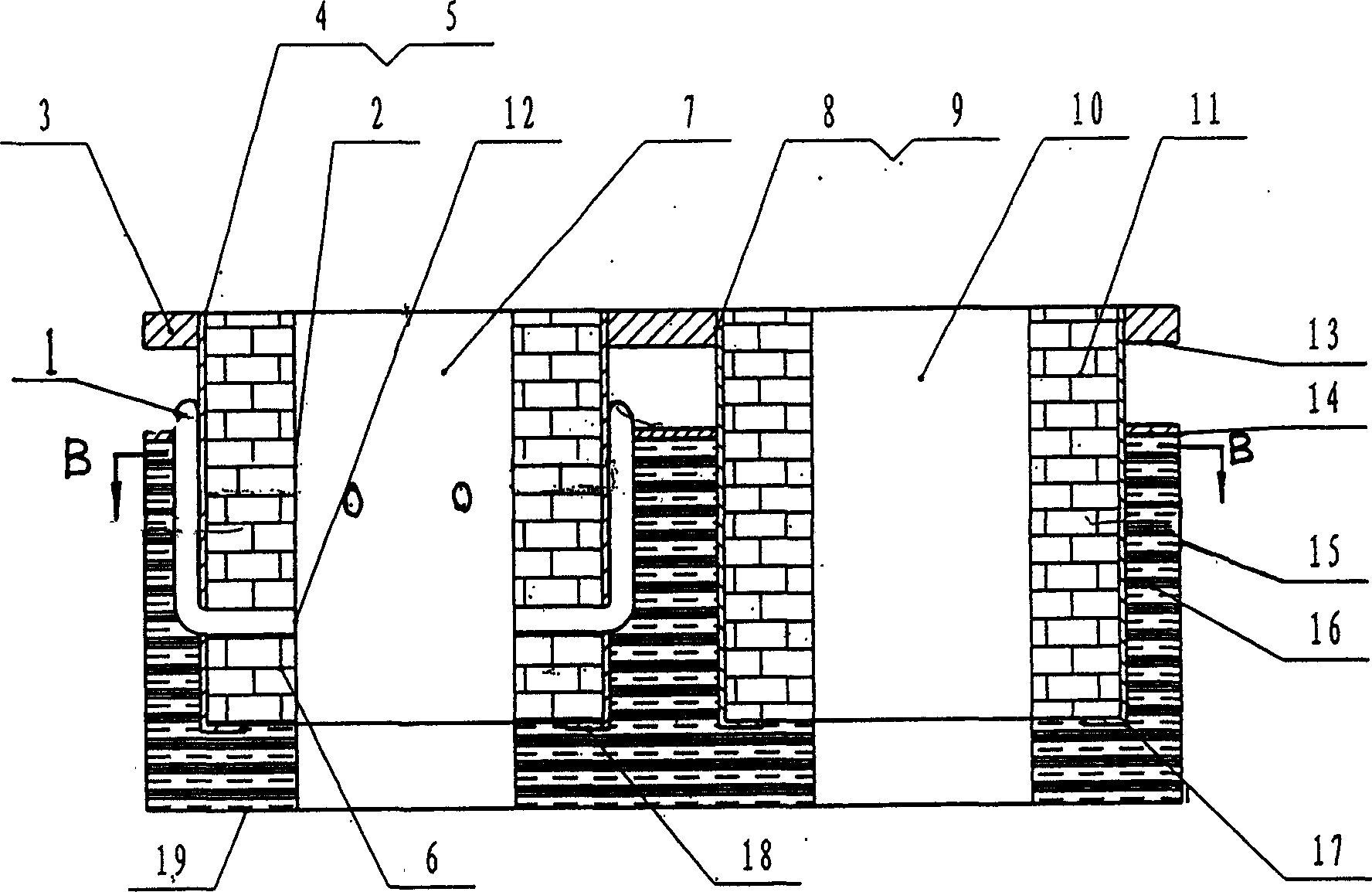
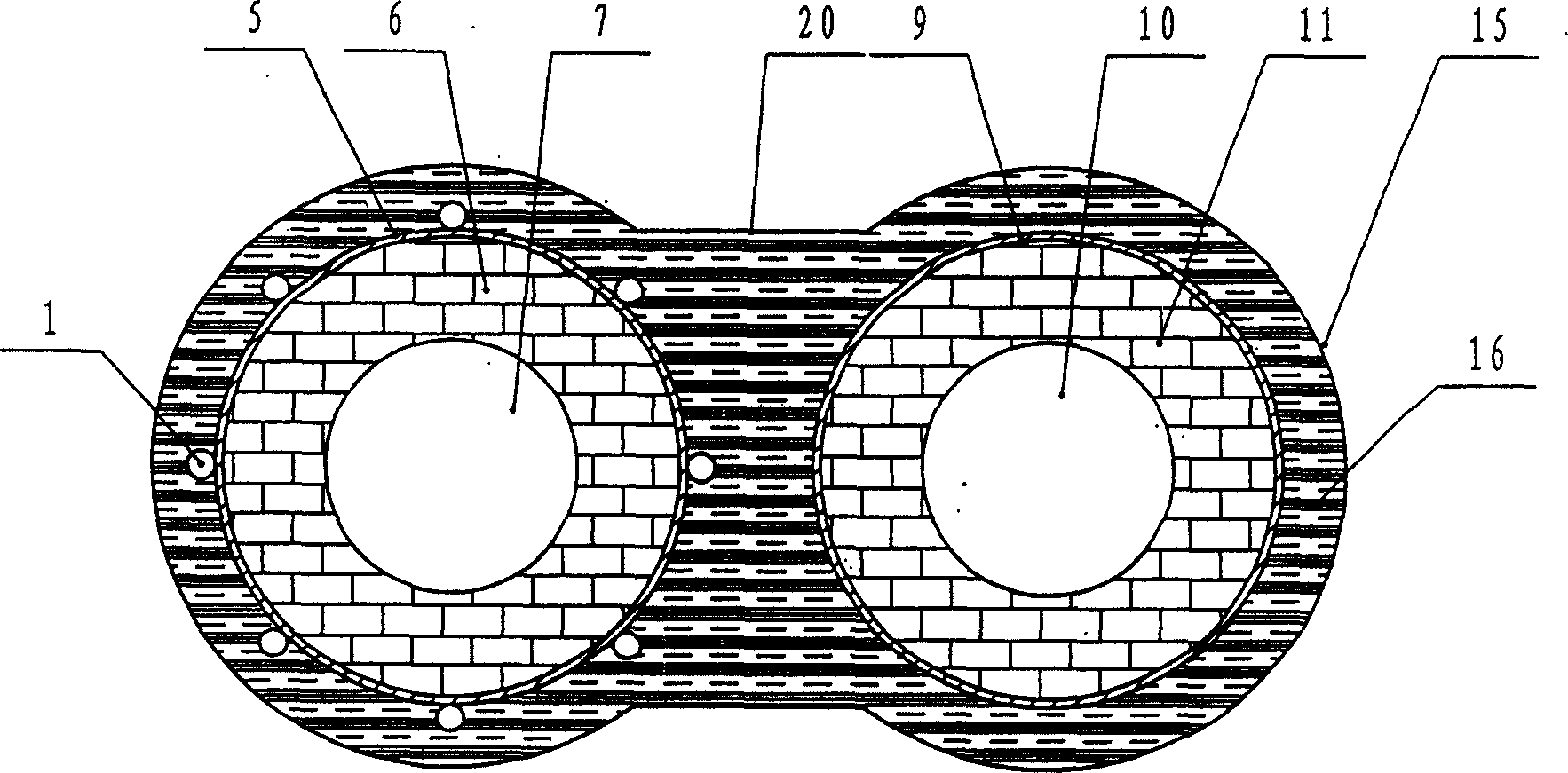
[0024] figure 1 , figure 2 and image 3 The described insertion tube for vacuum circulation degassing equipment includes a connecting flange, a steel cylinder, a refractory brick layer and a refractory cement sleeve. The lower opening of the steel cylinder is bent inward, and the upper opening of the steel cylinder is welded to the opening of the connecting flange. , the refractory cement sleeve is wrapped outside the steel cylinder, and the refractory brick layer is arranged in the steel cylinder. The inner side of the refractory brick layer is a through hole, and the through hole leads downward ...


PUM


Abstract

Disclosed is an insert tube of vacuum circulating degasification apparatus which comprises a coupling flange, a steel cylinder, a refractory brick layer and a fire proof cement sheath, wherein the coupling flange is provided with two apertures, the distance between the centers of the two apertures corresponds or is equal to the centers of the two coupling ports below the vacuum chamber of the vacuum recycled degasification equipment, each of the two apertures is connected with a steel cylinder through soldering, one of the steel cylinders is provided with 6-12 non-corrodible steel vent pipes around the through-holes of the refractory brick layer for letting in argon gas.

Description

technical field [0001] The invention relates to an insertion tube for vacuum cycle degassing equipment. Background technique [0002] Vacuum cycle degassing equipment was jointly designed and successfully tested by German Lule and Hailar companies in 1957. It is used for dehydrogenation of molten steel. After more than 40 years of development, vacuum cycle degassing equipment has the functions of dehydrogenation, carbon, oxygen, Sulfur, alloying, temperature control and many other functions. Now some iron and steel enterprises in the world have been widely used. This circulation degassing equipment has a vacuum chamber, and there are two insertion pipes below the vacuum chamber, one is an ascending pipe and the other is a descending pipe. Insert the insertion tube into the molten steel, vacuumize the vacuum chamber, and the molten steel is siphoned into the vacuum chamber from the ascending pipe, and then inert argon gas is introduced into the ascending pipe, so the densit...

Claims


Application Information

Patent Timeline
IPC IPC(8): C21C7/10
CPCY02P10/20
Inventor 张春亮
Owner SHANXI TAIGANG STAINLESS STEEL CO LTD
Why Eureka
Try Eureka