
Control process and control device of induction motor ind. appts.

A technology of an induction motor and a control method, which is applied in the direction of motor generator control, AC motor control, electronic commutation motor control, etc., can solve problems such as difficulty in obtaining high output

Inactive Publication Date: 2006-02-01
HITACHI LTD
View PDF0 Cites 7 Cited by
  • Summary
  • Abstract
  • Description
  • Claims
  • Application Information

AI Technical Summary

Problems solved by technology

[0003] However, during constant output operation above the base speed, it is difficult to obtain a high output above the rated output because control is performed to keep the internal induced electromotive force of the induction motor constant.

Method used


Image

  • Control process and control device of induction motor ind. appts.
  • Control process and control device of induction motor ind. appts.
  • Control process and control device of induction motor ind. appts.

Examples


Embodiment Construction

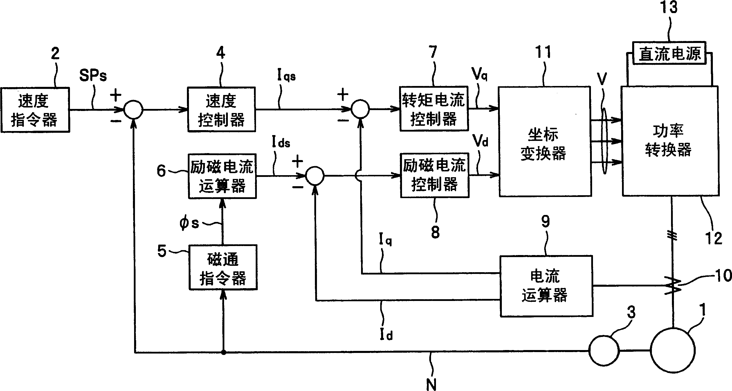
[0016] figure 1 , is a block diagram of the overall system including the control device for the induction motor according to the embodiment of the present invention.

[0017] figure 1 Among them, the induction motor 1 is driven according to the speed command SPs from the speed command device 2 . The speed command SPs is a target value of the rotational speed N (r / min). Furthermore, the induction motor 1 can be used, for example, in iron-making and non-ferrous equipment (hot-rolling equipment, cold-rolling equipment, processing line equipment), railway vehicles, coilers (including uncoilers), ships, construction machinery (for driving the main shaft) , paper machine equipment, conveying equipment and other purposes.

[0018] It will be specifically described below. The speed controller 4 outputs the torque current command Iqs to the torque current controller 7 based on the difference (SPs-N) between the speed command SPs and the rotational speed N of the induction motor 1 d...


PUM


Abstract

The invention aims at obtaining a high output above the rated output of an induction motor. When the magnetic field flux of the induction motor (1) is in a strong magnetic field flux status, according to an induction motor control method of carrying out the vector control of magnetic field weakening control, the magnetic field weakening control is carried out in case that the rotating speed N of the induction motor (1) is higher than a rated rotating speed. Furthermore, during carrying out the magnetic field weakening control, the magnetic field flux is changed to enable the internal inducted electromotive force of the induction motor (1) is larger than the rated rotating speed. In addition, after the magnetic field weakening control is started, the magnetic field flux is weakened according to the rise of the rotating speed N to enable the terminal voltage of the induction motor (1) not to exceed a crest voltage during a maximal overload.

Description

technical field [0001] The present invention relates to a control method and a control device of an induction motor, and particularly relates to a control method and a control device of an induction motor performing vector control. Background technique [0002] As a vector control method for an induction motor, the most general method for applying a DC separately excited motor is known. That is, the constant torque rotation is performed within the rated rotational speed (hereinafter referred to as "base speed"), and the constant output rotation is performed above the base speed. In addition, the rated rotational speed is the minimum rotational speed at the rated output as the reference output. This technique is described in, for example, "Non-Patent Document 1", "Application of Variable-speed AC Motors to Rolling Mills", Technical Report of the Society of Electrical Engineering, August 2015, No. 935, P.29. [0003] However, during constant output operation above the base s...

Claims


Application Information

Patent Timeline
IPC IPC(8): H02P21/00H02P21/22H02P23/07H02P23/16H02P27/04H02P27/08
CPCY02T10/643
Inventor 飞世正博永田宽小林清隆吉成良孝二藤部光弘松本久幸海老原一美
Owner HITACHI LTD
Learn More