Organic white light emitting diode in tiny cavity type

A technology of white light emission and diodes, which is applied in the direction of instruments, electrical components, circuits, etc., can solve the problems of white light color purity, color stability and low luminous efficiency, and achieve the problems of overcoming unstable luminous color, improving luminous efficiency, and enhanced luminous intensity Effect

Inactive Publication Date: 2006-02-01
CHANGCHUN INST OF OPTICS FINE MECHANICS & PHYSICS CHINESE ACAD OF SCI
View PDF0 Cites 19 Cited by
  • Summary
  • Abstract
  • Description
  • Claims
  • Application Information

AI Technical Summary

Problems solved by technology

[0005] The purpose of the present invention is to solve the problems of low color purity, color stability and luminous efficiency of white light in the above-mentioned background technology

Method used


Image

  • Organic white light emitting diode in tiny cavity type
  • Organic white light emitting diode in tiny cavity type
  • Organic white light emitting diode in tiny cavity type

Examples


Embodiment 1

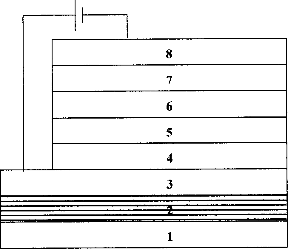
[0027] Embodiment 1: □ The structure of the organic microcavity light-emitting diode is:

[0028] Glass substrate / Bragg mirror / ITO / NPB / Alq / F-TBB / OXD-7 / MgAg, where the substrate is ordinary optical glass. The structure of the Bragg reflector is HLH, a total of three layers, of which the material of the H layer is TiO 2 , thickness 57.3nm; L layer material is LiF, thickness 97.5nm. The maximum reflectivity of the Bragg mirror is about 70%. The transparent conductive film ITO is used as the anode with a thickness of 300nm. The hole transport layer is made of NPB material with a thickness of 83nm. The light-emitting layer is made of Alq material with a thickness of 20nm. The material of the light-emitting layer Alq is a broad-spectrum light-emitting material with a fluorescence peak at 510nm and a spectral line half-width of 90nm. The hole blocking layer is made of F-TBB material with a thickness of 20nm. The electron transport layer is made of OXD-7 material with a thicknes...

Embodiment 2

[0034] Embodiment 2: the structure that microcavity device adopts is: the structure of glass / Bragg reflector / ITO(156nm) / NPB(97nm) / Alq(72nm) / MgAg(150nm) Bragg reflector is three-layer HLH, wherein H Layer material is ZrO 2 / TiO 2 The mixture has a refractive index of 2.2 and a thickness of 62nm; the material of the L layer is LiF with a refractive index of 1.41 and a thickness of 98nm. The maximum reflectivity of the Bragg mirror is 60%. Depend on Figure 12 It can be seen that the electroluminescence spectrum of the microcavity device has two luminescence peaks, which are located at 467nm and 616nm. The luminescent color is white, and its 1931 CIE color coordinates are (0.357, 0.30) such as Figure 13 shown.


PUM


Abstract

The invention solves issues of color purity of white color, stability of color and luminous efficiency. The disclosed diode includes substrate, Bragg reflection mirror, anode, hole transport layer, luminous layer, cavity barrier layer, electron transport layer, and cathode. Through structure of micro cavity, changing luminous characters of broadband of organic material, the invention realizes irradiance in two modes of resonance in visible range, making match of spectrum generate white light. Since luminous layer is positioned near to antinode of stationary field intensity in two modes of resonance in micro cavity, luminous intensities in two modes are enhanced, and luminous efficiency is increased. Under condition of not changing length of cavity, adjusting relative position of luminous layer changes relative luminous intensities between two modes to optimize color purity. Features are: stable white light and raised luminous efficiency.

Description

Technical field: [0001] The invention belongs to the technical field of light emission and display, and relates to the structural design and preparation method of an organic white light emitting diode. Background technique: [0002] Organic light-emitting diodes are a flat panel display technology developed in recent years, and have broad application prospects. This type of device is an electrically driven light-emitting device composed of multiple organic layers plus electrodes. Red, blue, green and white organic light emitting diodes have been realized using organic light emitting materials. Among them, white organic light-emitting diodes have important applications in green lighting, backlight sources of liquid crystal screens, and the like. Most small organic molecules and polymer luminescent materials have a wide luminescent band (typical half-width is about 100nm), so their luminescent color is neither pure monochromatic nor pure white. The main preparation method o...

Claims


Application Information

Patent Timeline
Patent Type & Authority Applications(China)
IPC IPC(8): H01L51/50H01L33/00G09F9/33
Inventor 刘星元
Owner CHANGCHUN INST OF OPTICS FINE MECHANICS & PHYSICS CHINESE ACAD OF SCI
Why Eureka
Try Eureka