
Method for increasing linearity of feedforward power amplifier using carrier leakage effect

A power amplifier, carrier leakage technology, applied in power amplifiers, improving amplifiers to reduce nonlinear distortion, etc., can solve the increase in hardware complexity, the overall cost of feedforward power amplifiers, and the lack of adaptive characteristics of carrier leakage. problem, to achieve the effect of improving linearization performance

Inactive Publication Date: 2006-01-25
HUAWEI TECH CO LTD
View PDF0 Cites 4 Cited by
  • Summary
  • Abstract
  • Description
  • Claims
  • Application Information

AI Technical Summary

Problems solved by technology

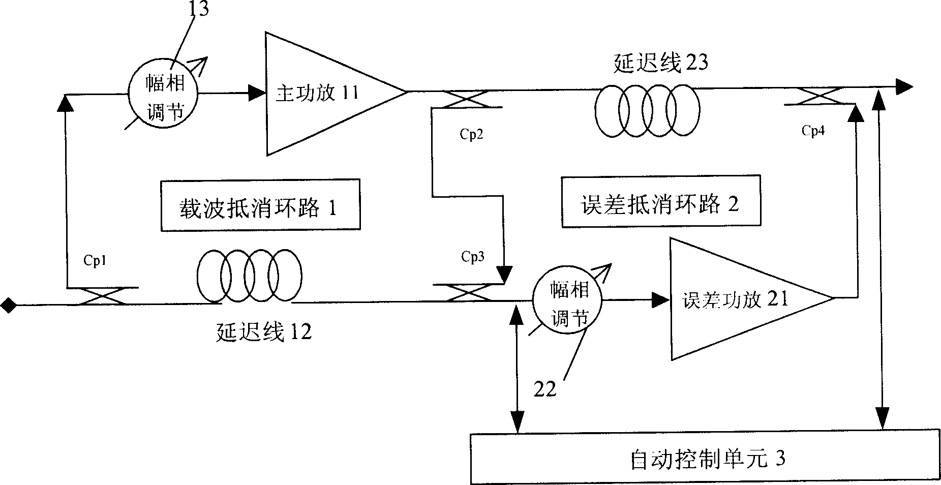
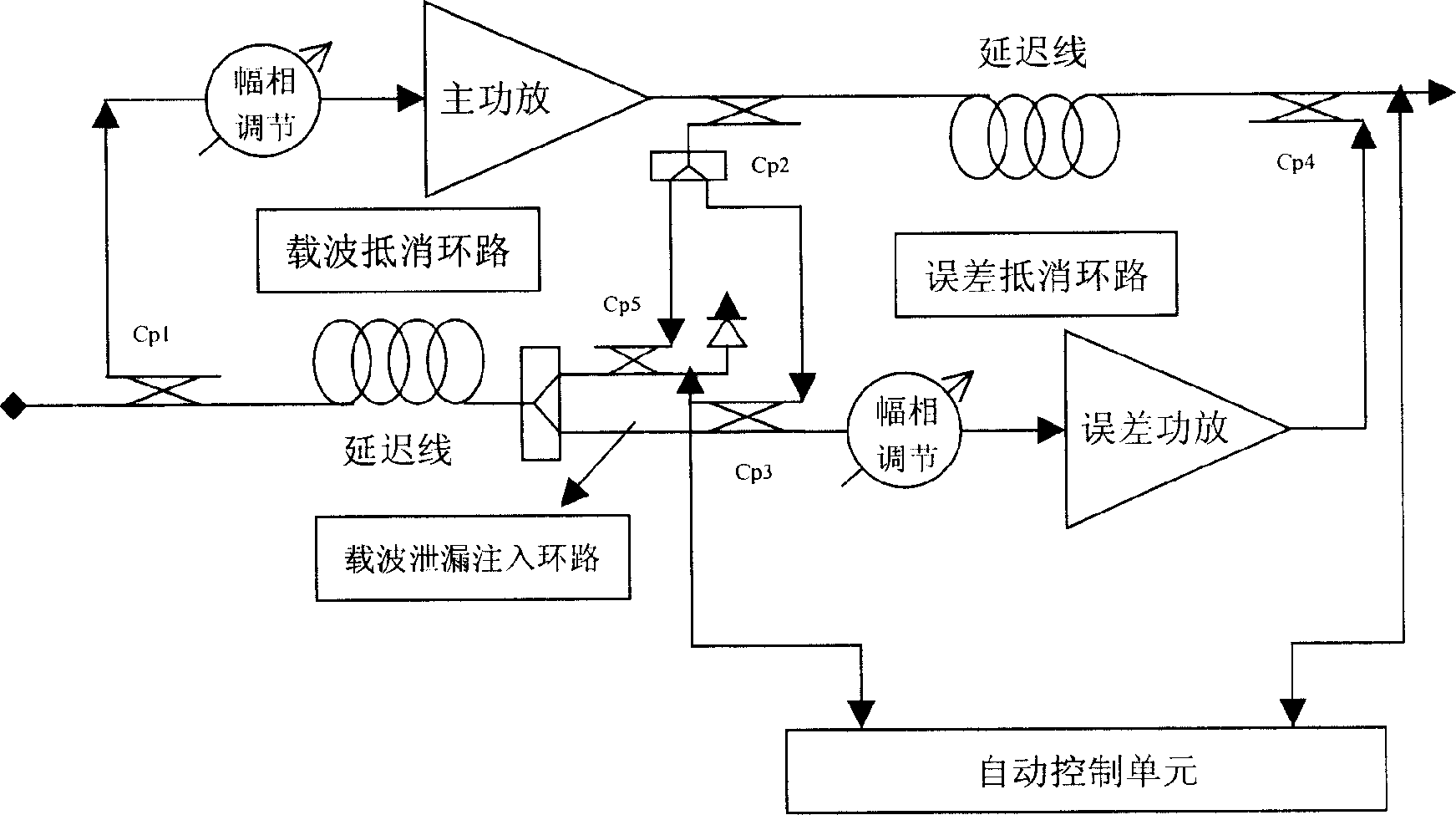
[0014] The disadvantages of this prior art are: due to the addition of a carrier leakage injection loop, the hardware complexity increases, the overall cost of the feed-forward power amplifier is increased, and due to the amplitude difference and phase of the Cp3 and Cp5 coupling paths The difference is a fixed value, so the magnitude of the carrier leakage is not adaptive

Method used


Image

  • Method for increasing linearity of feedforward power amplifier using carrier leakage effect
  • Method for increasing linearity of feedforward power amplifier using carrier leakage effect
  • Method for increasing linearity of feedforward power amplifier using carrier leakage effect

Examples


Embodiment Construction

[0037] Such as figure 1 As shown, the structure of the feedforward power amplifier in the prior art is mainly composed of a carrier cancellation loop 1 , an error cancellation loop 2 and an automatic control unit 3 . The carrier cancellation loop 1 mainly includes a main power amplifier 11 , a delay line 12 and an amplitude-phase regulator 13 , and the error cancellation loop 2 mainly includes an error power amplifier 21 , an amplitude-phase regulator 22 and a delay line 23 . The hardware structure of the feedforward power amplifier of the present invention is basically the same as the hardware structure of the feedforward power amplifier in the prior art, but the adaptive control method in the automatic control unit 3 of the feedforward power amplifier is improved, Allowing carrier cancellation loop 1 to properly leak some carrier power can produce a better linear effect than complete cancellation.

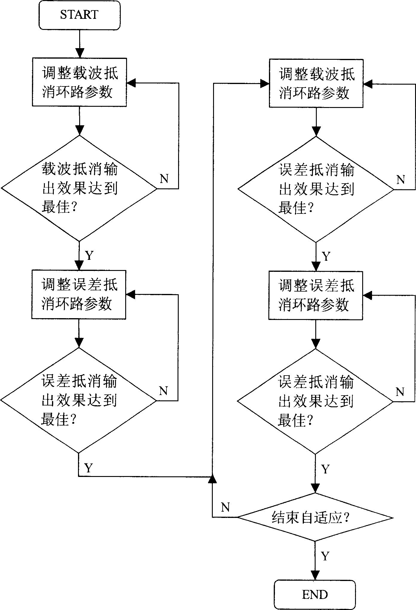
[0038] Such asfigure 1 , image 3 As shown, the method for improving the l...


PUM


Abstract

A method for raising linearity of feed forward power amplifier by utilizing carrier leakage effect includes finding out loop convergent initial adapting point to make both counterbalance loops of carrier wave and error be convergent state , searching convergent point of carrier wave leakage effect , adjusting parameters of carrier wave loop and error counterbalance loop to let carrier wave counterbalance loop leak out carrier wave energy and to let error counterbalance loop output inter-modulation signal with minimum power value .

Description

technical field [0001] The invention relates to a method for improving the performance of a feedforward power amplifier, in particular to a method for improving the linearity of the feedforward power amplifier by utilizing the carrier leakage effect. Background technique [0002] With the rapid development of global communication technology, communication spectrum resources are becoming more and more scarce. In order to use spectrum resources more effectively, many communication systems use modulation methods with high spectrum utilization, such as QPSK (phase shift keying), 8PSK (eight phase shift keying) and so on. These modulation methods modulate the amplitude and phase of the carrier at the same time, so these modulation methods will produce a non-constant envelope modulation signal with a large peak-to-average ratio. The large peak-to-average ratio puts forward high linearity requirements for the power amplifier of the RF transmitter, because the power amplifier has u...

Claims


Application Information

Patent Timeline
IPC IPC(8): H03F1/32H03F3/20
Inventor 蔡文超
Owner HUAWEI TECH CO LTD
Learn More