Method for keeping output of liquid and gas fuel at constant pressure

A liquid fuel and gaseous fuel technology, which is applied in the direction of combustion method, liquid fuel supply/distribution, etc., can solve the problems of easy leakage of gaseous fuel, environmental pollution, and uneconomic benefits

Inactive Publication Date: 2005-11-16
凯尔优企业有限公司
View PDF1 Cites 2 Cited by
  • Summary
  • Abstract
  • Description
  • Claims
  • Application Information

AI Technical Summary

Problems solved by technology

[0004] 1. Since the air input unit and fuel output unit of the aforementioned steel cylinder are fixed on the cover and cannot be disassembled, when the liquid fuel inside the steel cylinder is used up, the entire set of steel cylinder equipment (including the air input unit and fuel on it) must be removed. output unit) together, but the steel cylinder is relatively heavy, and its handling process is cumbersome and dangerous. In addition, due to the high manufacturing cost of the steel cylinder itself, its design needs to be improved
[0005] 2. The joint of the above-mentioned fuel delivery device is only equipped with a permeation tube that can inject gas and be in contact with the fuel, but the permeation tube is not enough to completely mix the liquid in the container body space and gasify it into a combustible gas, so there is often Part of the liquid fuel remains at the bottom of the steel cylinder, which is neither economical nor environmentally friendly, and the residue is often harmful; and in order to solve the above-mentioned defects of the steel cylinder, when the general user wants to use the fuel at the bottom of the steel cylinder completely to save energy, only Shaking the cylinder with external force, or even laying the cylinder horizontally, so that the fuel can flow out of the cylinder, and this method of use is also very dangerous
[0006] 3. The above-mentioned fuel delivery device is only assembled on the assembly port of the steel cylinder through the cover body, and the gaseous fuel inside the steel cylinder is often easily leaked due to careless assembly.
[0007] 4. The above-mentioned fuel delivery device is only suitable for closed oil storage containers, such as existing steel cylinders
[0009] However, this prior art still needs to disassemble the extraction device to add fuel to the oil storage container. Because the extraction device is in contact with the oily fuel, when it is disassembled, the extraction device is still contaminated with fuel, which may easily cause the fuel to drip onto the ground. And pollute the environment, there are defects in use, and the above-mentioned oil storage container and pick-up device are arranged together, because the volume of the oil storage container is huge, it takes up a lot of space and cannot be placed indoors, but can only be placed outdoors, so use At the same time, the extraction device needs to pull a long pipeline to connect to the burning appliance such as a gas stove. The long pipeline is likely to cause insufficient pressure, and when the gas furnace burns, it will cause unstable combustion and cause danger.

Method used


Image

  • Method for keeping output of liquid and gas fuel at constant pressure
  • Method for keeping output of liquid and gas fuel at constant pressure
  • Method for keeping output of liquid and gas fuel at constant pressure

Examples


Embodiment Construction

[0023] Relevant detailed description and technical contents of the present invention are as follows now in conjunction with the accompanying drawings:

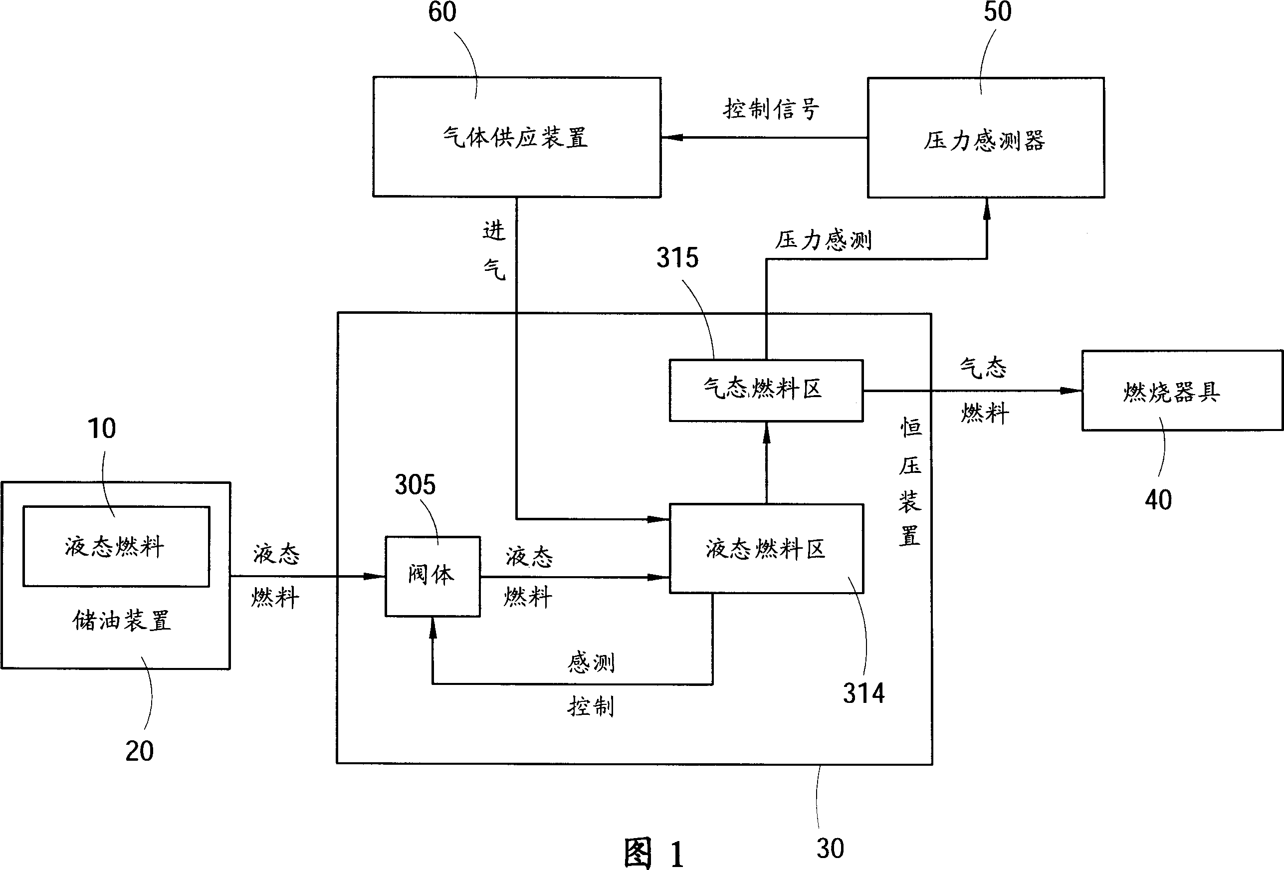
[0024] Please refer to Fig. 1, which is a schematic diagram of the program according to the present invention, as shown in the figure, it includes: an oil storage device 20, which is used for a kind of liquid fuel 10 to be input and accommodated therein, and the oil storage device 20 passes through a valve When the body 305 is opened, the liquid fuel 10 in the oil storage device 20 is output to a constant pressure device 30, and reaches a preset liquid level, and a liquid fuel zone 314 and a liquid fuel area 314 are defined in the constant pressure device 30 according to the liquid level. A gaseous fuel area 315, so that the gas supply device 60 can input gas to the liquid fuel area 314 of the constant pressure device 30 to be gasified into a gaseous fuel, and then output the gaseous fuel to a burner 40 such as a gas stove for ...


PUM


Abstract

The present invention discloses a method for making liquid gas fuel retain output constant pressure. Said method utilies the retention of mixing ratio of liquid fuel and gas fuel in the constant pressure device to make the constant pressure device output gas fuel with stable pressure and supply said gas fuel for burner.

Description

technical field [0001] The invention relates to a method for maintaining a constant output pressure of a liquid gas fuel, in particular to a gaseous fuel which enables a constant pressure device to output a stable pressure. Background technique [0002] Existing containers for storing or transporting volatile fuels are generally steel cylinders, which mainly include a bottle body with a certain accommodation space, a feeding port is opened on the top of the bottle body, and a cover is fixed on the feeding port body, the cover is provided with an air input unit and a fuel output unit, wherein the air input unit includes a group of joints arranged on the cover and communicated with the accommodating space of the bottle body, at one end of the joint A permeation pipe is extended, and an output pipe is externally connected to the other end of the group joint, and the output pipe is connected to a gas supply device that can be a pump, and the fuel output unit includes a group of ...

Claims


Application Information

Patent Timeline
Patent Type & Authority Applications(China)
IPC IPC(8): F23K5/10
Inventor 余政忠刘文楷
Owner 凯尔优企业有限公司
Why Eureka
Try Eureka