Tooth edge float valve
A technology of float valve and tooth edge, applied in the field of float valve, can solve the problems of uneven gas holdup rate and bubble size of foam layer, unsatisfactory treatment efficiency of float valve tray, large liquid level drop, etc., to reduce the liquid level drop , Increase the gas-liquid contact area and reduce the resistance effect
- Summary
- Abstract
- Description
- Claims
- Application Information
AI Technical Summary
Problems solved by technology
Method used
Image
Examples
Embodiment 1
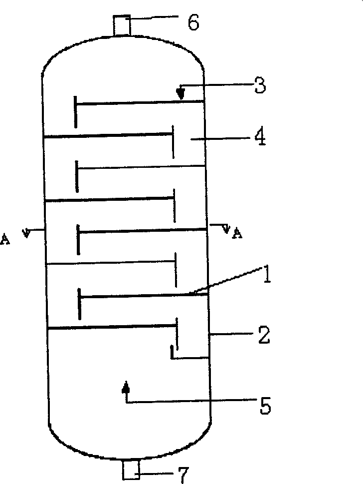
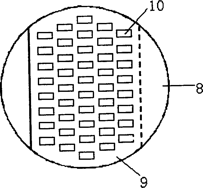
[0028] refer to figure 1 , figure 2 , several trays 1 equipped with serrated edge float valves according to the present invention are installed in the vertical column 2 in sequence. Liquid is introduced from a liquid supply line 3 to the upstream end of the uppermost tray. Downcomers 4 direct liquid from the downstream end of a higher tray to the upstream end of an adjacent lower tray. The gas is introduced under the lowermost tray through the gas supply line 5, and the gas enters the liquid on the tray through the serrated float valve on the tray. The top of the vertical tower is provided with a gas discharge port 6, and the bottom is provided with a liquid discharge port 7. There is a liquid receiving area 8 on each tray, which accepts the liquid from the downcomer 4, and the liquid comes out of the downcomer 4 and falls into the liquid receiving area 8, and then turns to flow to the bubbling area 9 provided with tooth edge float valves. . A valve hole 10 is opened in ...
Embodiment 2
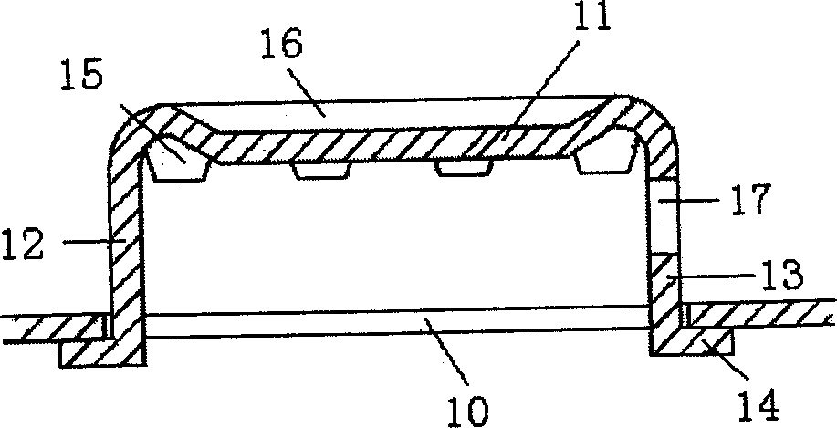
[0035] refer to image 3 , 4, A wedge-shaped groove 16 is opened on the valve cover 10 . The wedge-shaped groove 16 can guide the flow of gas to both sides of the valve hole of the upper tray, avoiding the formation of air flow vortex under the float valve, reducing the back mixing of liquid and the resistance of gas passing through the float valve. The shape of the cross-section of the wedge-shaped groove 16 can be various, such as Figure 7-9 V-shaped, arc-shaped, inverted trapezoid, etc. shown.
[0036] The rest of the structure and implementation are the same as in Embodiment 1.
Embodiment 3
[0038] refer to image 3 , Figure 4 , A liquid guide hole 17 is opened on the back liquid valve leg 13, and the liquid guide hole 17 can push the liquid to flow to the outlet weir through the gas, which reduces the liquid level drop and reduces the liquid back-mixing. The liquid guide hole 17 is opened on the back liquid valve leg. When the gas volume passing through the float valve is small, the float valve does not float, and the liquid guide hole 17 is below the tray. Therefore, the opening of the liquid guide hole 17 will not raise the float. The lower operating limit of the valve tray. The shape of the liquid guide hole 17 can be various, such as Figure 16-21 Shown are circles, ovals, rectangles, trapezoids, triangles, rhombuses, etc.
[0039] The rest of the structure and implementation are the same as in Embodiment 1.
PUM
 Abstract
Description
Claims
Application Information
 - R&D
- Intellectual Property
- Life Sciences
- Materials
- Tech Scout
- Unparalleled Data Quality
- Higher Quality Content
- 60% Fewer Hallucinations
Browse by: Latest US Patents, China's latest patents, Technical Efficacy Thesaurus, Application Domain, Technology Topic, Popular Technical Reports.
© 2025 PatSnap. All rights reserved.Legal|Privacy policy|Modern Slavery Act Transparency Statement|Sitemap|About US| Contact US: help@patsnap.com


