
Welding method and circuit board using same

A welding method and circuit board technology are applied in the direction of assembling printed circuits, circuits, and printed circuits with electrical components. The effect of good electrical conduction

Inactive Publication Date: 2005-10-05
DEYI PRECISION ELECTRONIC IND CO LTD PANYU
View PDF0 Cites 0 Cited by
  • Summary
  • Abstract
  • Description
  • Claims
  • Application Information

AI Technical Summary

Problems solved by technology

However, due to the bending deformation of the electrical connector caused by heating, the relative position of the electrical connector and the circuit board is shifted, and a gap is formed between the conductive terminal and the conductive sheet, so that the conductive terminal and the conductive sheet cannot be welded together. , thus affecting the normal conduction between the circuit board and the electrical connector

Method used


Image

  • Welding method and circuit board using same
  • Welding method and circuit board using same
  • Welding method and circuit board using same

Examples


Embodiment Construction

[0017] The present invention will be further elaborated below in conjunction with the accompanying drawings and specific embodiments.

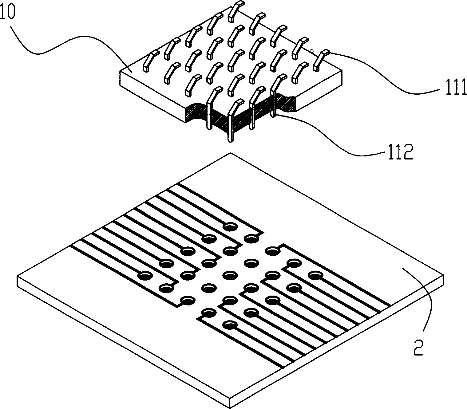
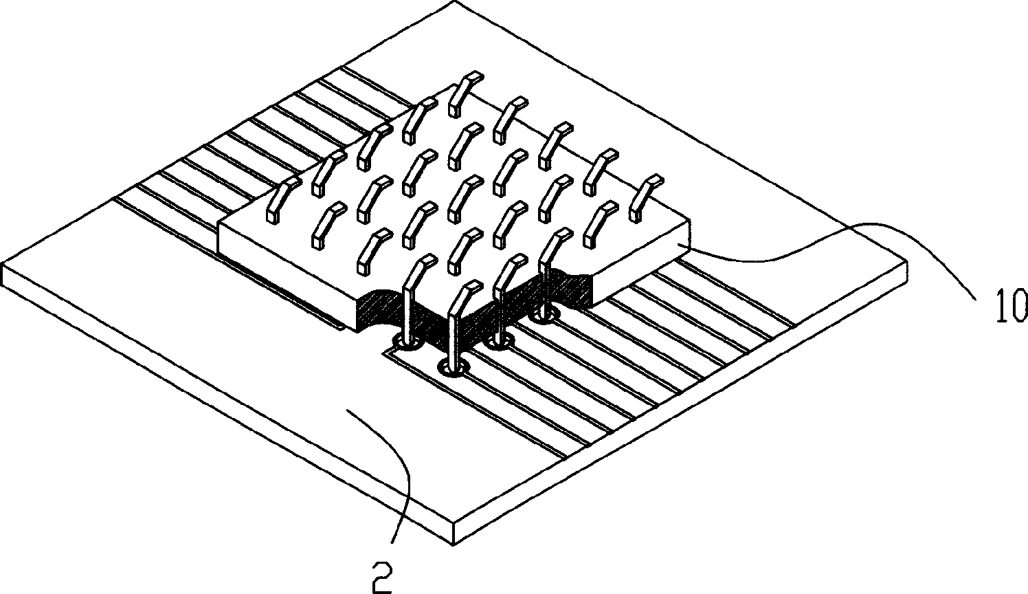
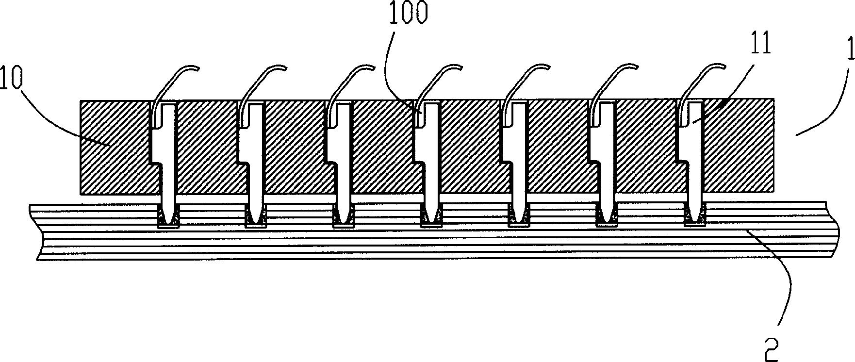
[0018] refer to Figure 1 to Figure 4 , The welding method of the present invention can weld two electronic components together, and these two electronic components can be any other electronic components such as chips or circuit boards. Now only the soldering of the electrical connector to the circuit board using this soldering method will be described in detail.

[0019] Wherein the electrical connector 1 includes an insulating body 10 and a needle-shaped welding end (conductive terminal 11 in this example), the insulating body 10 is provided with a terminal receiving hole 100, and the conductive terminal 11 is placed in the terminal receiving hole 100 of the insulating body 10, It includes a holding part 110, a contact part 111 extending upward from the holding part 110, and a needle-shaped welding part 112 extending downward from the holdi...


PUM


Abstract

The present invention relates to a welding method capable of welding two electronic elements together, in which on one electronic element a needle welding end is set, on another electronic element several holes with weltable portion and welding compound correspondent to the holes, the needle welding end can be inserted into the hole, and can be welded with described weltable portion by heating welding compound. Said invention can make two electronic elements be connected together stably.

Description

【Technical field】 [0001] The invention relates to a welding method and a circuit board using the welding method. 【Background technique】 [0002] Currently, electrical connectors are soldered to circuit boards, see Figure 8 , Figure 9 As shown, generally, the solder paste is directly placed on the conductive sheet provided on the circuit board, and the conductive terminal of the electrical connector is welded to the conductive sheet by melting the solder paste to realize electrical connection. However, due to the bending deformation of the electrical connector caused by heating, the relative position of the electrical connector and the circuit board is shifted, and a gap is formed between the conductive terminal and the conductive sheet, so that the conductive terminal and the conductive sheet cannot be welded together. , thus affecting the normal conduction between the circuit board and the electrical connector. [0003] Therefore, it is necessary to invent a new electri...

Claims


Application Information

Patent Timeline
Patent Type & Authority Applications(China)
IPC IPC(8): B23K1/00H01R13/24H01R43/02H05K3/34
CPCH01R13/2442B23K1/0016H01R43/0249H05K3/3421H05K2201/09472H05K2201/09509H05K2201/10189H05K2201/10704Y02P70/50
Inventor 张文昌
Owner DEYI PRECISION ELECTRONIC IND CO LTD PANYU
Learn More