
Capacitor wiring device

A wiring device and capacitor technology, applied in the direction of capacitors, multiple fixed capacitors, fixed capacitor terminals, etc., can solve the problems of rising labor costs, messy overall structure, large workload, etc., to improve the level of automation, improve disassembly and assembly Convenience, easy electrical conduction effect

Pending Publication Date: 2022-02-11
惠州市先锋电镀设备有限公司
View PDF0 Cites 0 Cited by
  • Summary
  • Abstract
  • Description
  • Claims
  • Application Information

AI Technical Summary

Problems solved by technology

[0003] However, the filter circuit and the full-bridge rectifier circuit have many connection points as well as the connection points between the two circuits, and multiple wires need to be used for interpenetrating connection. The interpenetrating connection method of multiple wires has the following defects: First, because There are many connection points and connecting wires, and the overall structure is messy and complicated. Second, due to the large number of connections and contacts, the workload of stripping wires and welding wire earmuffs, shrinking tubes, and coding tubes during connection is heavy, which directly leads to increased labor costs.

Method used


Image

  • Capacitor wiring device
  • Capacitor wiring device
  • Capacitor wiring device

Examples


Embodiment Construction

[0028] In order to facilitate the understanding of the present invention, the present invention will be described more fully below with reference to the associated drawings. Preferred embodiments of the invention are shown in the accompanying drawings. However, the present invention can be embodied in many different forms and is not limited to the embodiments described herein. On the contrary, the purpose of providing these embodiments is to make the disclosure of the present invention more thorough and comprehensive.

[0029] It should be noted that when an element is referred to as being “fixed” to another element, it can be directly on the other element or there can also be an intervening element. When an element is referred to as being "connected to" another element, it can be directly connected to the other element or intervening elements may also be present. The terms "vertical," "horizontal," "left," "right," and similar expressions are used herein for purposes of ill...


PUM


Abstract

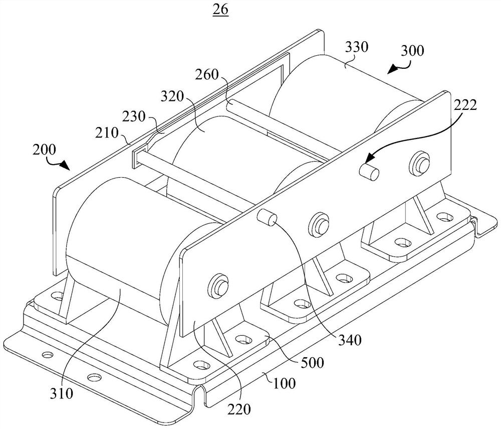
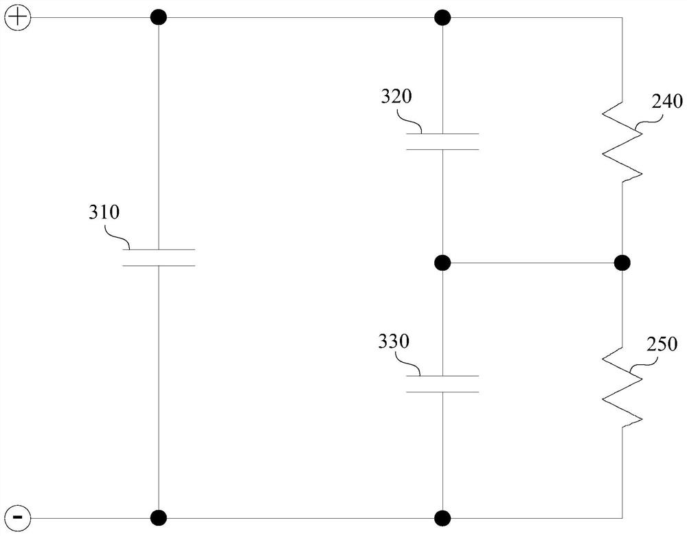
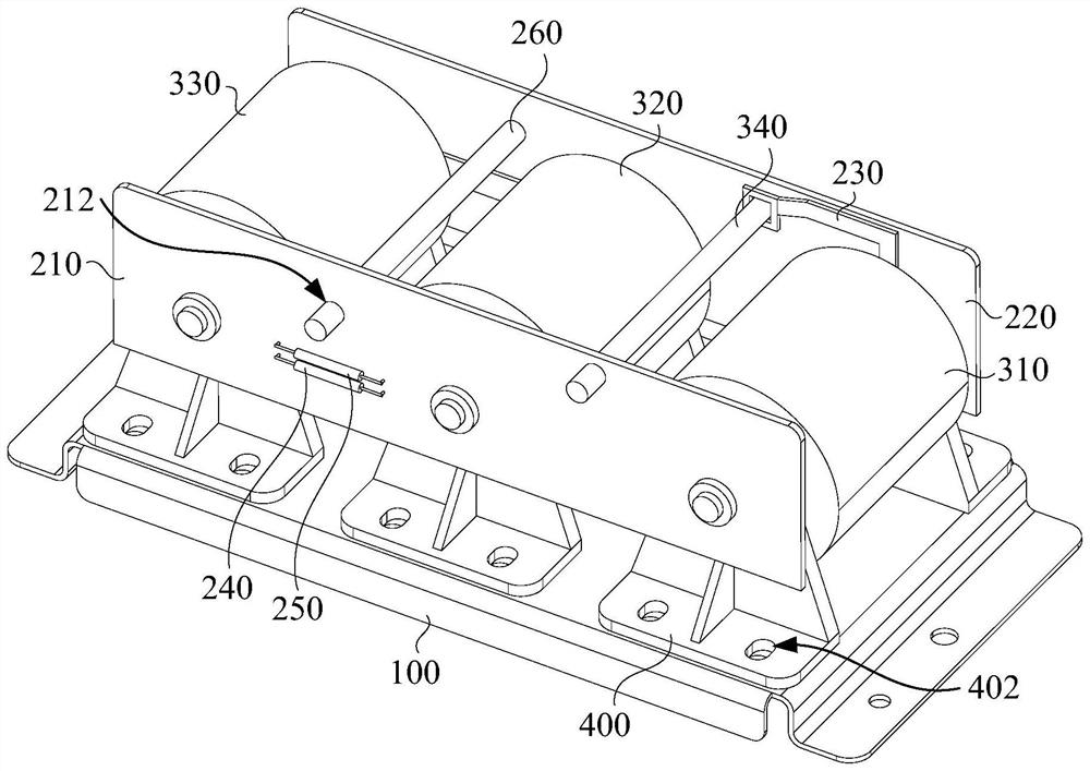
The invention provides a capacitor wiring device. The capacitor wiring device comprises a wire board assembly and a capacitor assembly. The circuit board assembly comprises a first circuit board and a second circuit board which are oppositely arranged, and a plurality of conductive circuits are arranged in the first circuit board and the second circuit board; the capacitor assembly comprises a first electrodeless capacitor, a second electrodeless capacitor, a third electrodeless capacitor and a first bridge type conductive piece, the first end of the first electrodeless capacitor is electrically connected with the first end of the second electrodeless capacitor, and the second end of the second electrodeless capacitor is electrically connected with the second end of the third electrodeless capacitor; the first end of the first bridge type conductive piece is connected with the first end of the third electrodeless capacitor, and the second end of the first bridge type conductive piece is connected with the second end of the first electrodeless capacitor. The electrodeless capacitors are connected through the conductive circuits on the circuit board and do not need to be connected through wires in an interpenetrating mode.

Description

technical field [0001] The invention relates to the technical field of connectors, in particular to a capacitor connecting device. Background technique [0002] At present, in the industrial high-frequency rectifying power supply industry, since the input used is high-frequency alternating current, in order to provide stable direct current, it usually needs to go through a rectifier circuit and a filter circuit. Among them, the filter circuit usually uses a large-capacity capacitor to meet The withstand voltage of the external high voltage, and the rectification circuit usually uses a rectifier bridge circuit, for example, using an insulated gate bipolar transistor (IGBT, Insulated Gate Bipolar Transistor) or a metal-oxide semiconductor field-effect transistor (MOSFET, Metal-Oxide- Semiconductor Field-Effect Transistor) forms a full-bridge rectifier circuit. [0003] However, the filter circuit and the full-bridge rectifier circuit have many connection points as well as the...

Claims


Application Information

Patent Timeline
Patent Type & Authority Applications(China)
IPC IPC(8): H01G4/38H01G4/228H01G2/06H01R12/71
CPCH01G4/38H01G4/228H01G2/06H01R12/71
Inventor 梁德新向啟平孔令伟李辉
Owner 惠州市先锋电镀设备有限公司
Learn More