Comparator circuit

A comparator circuit and comparator technology, which are applied in the layout of amplifier protection circuits, logic circuits with logic functions, multiple input and output pulse circuits, etc., can solve problems such as inability to correspond, and achieve the effect of reducing the number of components

Inactive Publication Date: 2005-09-28
SANYO ELECTRIC CO LTD
View PDF1 Cites 3 Cited by
  • Summary
  • Abstract
  • Description
  • Claims
  • Application Information

AI Technical Summary

Problems solved by technology

Therefore, it cannot correspond to a wide range of standards that require an input voltage range of Vss to Vdd

Method used


Image

  • Comparator circuit
  • Comparator circuit
  • Comparator circuit

Examples


Embodiment Construction

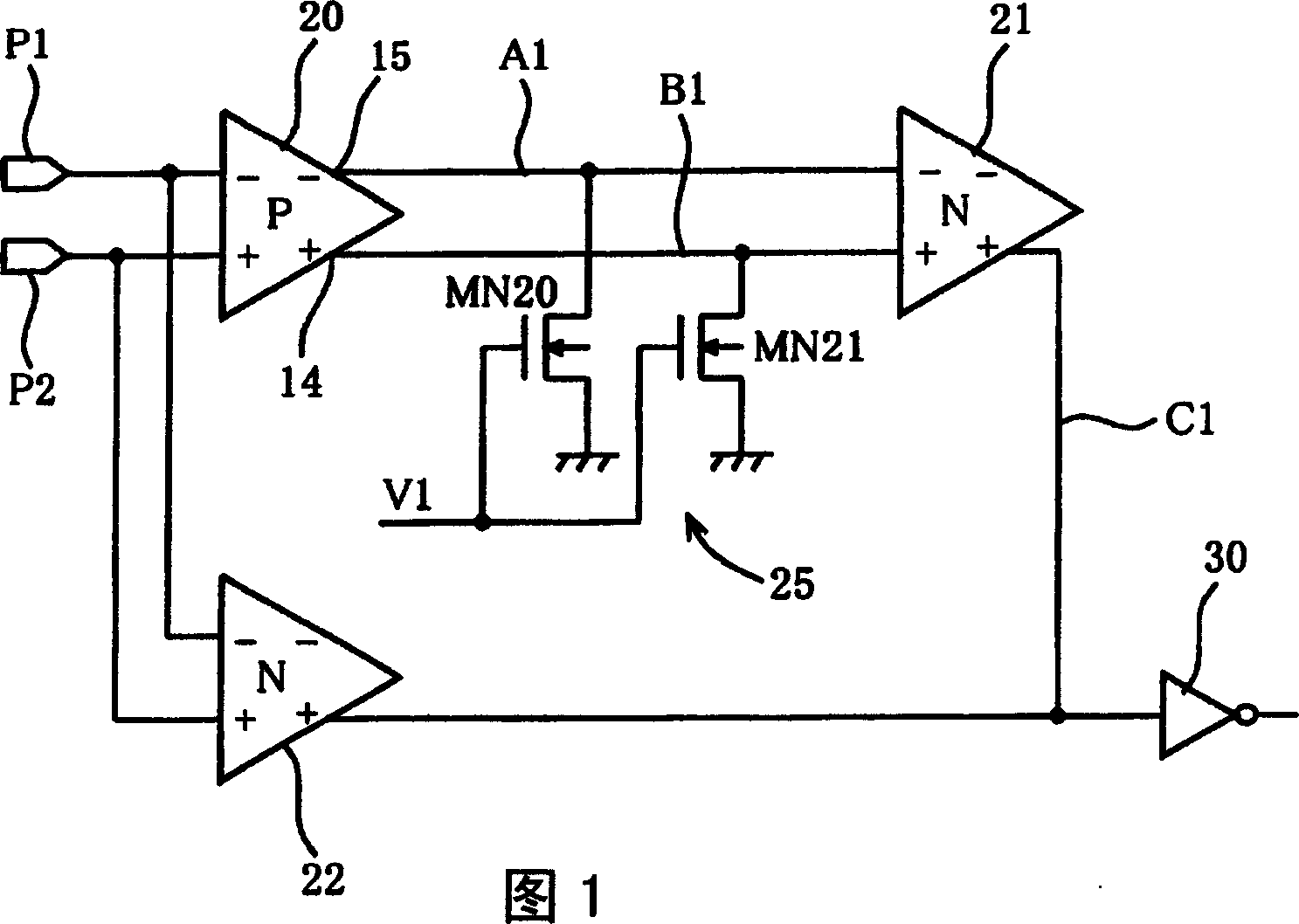
[0018] Next, a comparator circuit according to a first embodiment of the present invention will be described with reference to the drawings. Figure 1 is a circuit diagram of the comparator circuit.

[0019] The comparator circuit includes a first comparator 20 receiving a pair of differential input signals from input terminals P1, P2, a second comparator 21 receiving a pair of differential outputs of the first comparator 20, The second comparator 21 is synthesized by a pair of differential output terminals of a comparator 20, a current source 25 through which a small current flows to the ground voltage Vss, and a third comparator 22 receiving a pair of differential input signals from the input terminals P1 and P2. The differential output of the third comparator 22 and the differential output of the third comparator 22 become output signals. This output signal is received by an inverter 30 of the next stage.

[0020] Here, the first comparator 20 is with Figure 5 The same c...


PUM


Abstract

The present invention provided a comparator circuit operating normally over a wide input voltage range of Vss to Vdd. The comparator circuit comprises a first comparator 20 receiving a pair of differential input signals from input terminals P1 and P2, a second comparator 21 receiving a pair of differential outputs from the first comparator 20, a current source 25 for feeding a very small current from a pair of differential output terminals of the first comparator 20 to the ground voltage Vss, and a third comparator 22 receiving a pair of differential input signals from the input terminals P1 and P2 wherein the differential outputs from the second comparator 21 and the third comparator 22 are synthesized to produce an output signal. The output signal is received by an inverter 30 on the next stage. The first comparator 20 is a P type comparator and the second and third comparators 21 and 22 are N type comparators.

Description

technical field [0001] This invention relates to comparator circuits for comparing a pair of differential input signals. Background technique [0002] In recent years, when transmitting high-frequency signals, in order to suppress the influence of noise, etc., transmission in the form of differential signals has been widely carried out. In the case of receiving such a differential signal on the LSI side, a comparator is generally used to form an interface. For example, when connecting a USB cable to a microcomputer, an interface including a comparator is provided on the microcomputer (Patent Document 1). [0003] Figure 4 It is a circuit diagram showing a conventional comparator. Such as Figure 4 As shown in (a), the comparator is composed of a pair of N-channel differential MOS transistors MN1 and MN2 , a pair of P-channel MOS transistors MP1 and MP2 connected to a current mirror, and a constant current source 1 . The gate of the differential MOS transistor MN1 corresp...

Claims


Application Information

Patent Timeline
Patent Type & Authority Applications(China)
IPC IPC(8): H03K5/08H03F1/52H03F3/08H03F3/45H03F3/68H03K5/22H03K5/24
CPCH03K5/2481H03K19/20H03F3/45
Inventor 菅野崇志
Owner SANYO ELECTRIC CO LTD
Why Eureka
Try Eureka