
Laminated ceramic capacitor

A technology of ceramic capacitors and laminates, which is applied in the direction of laminated capacitors, fixed capacitor electrodes, multiple fixed capacitors, etc., can solve the problems of poor yield and poor connection of terminal electrodes, etc. The occurrence of cracks is reduced and the yield is good

Active Publication Date: 2005-09-14
TDK CORP
View PDF2 Cites 10 Cited by
  • Summary
  • Abstract
  • Description
  • Claims
  • Application Information

AI Technical Summary

Problems solved by technology

[0005] Therefore, in a laminated ceramic capacitor having a plurality of terminal pairs, compared with a general laminated ceramic capacitor, the part where the internal electrodes exposed on the side surface of the ceramic main body is less often has poor connection with the terminal electrodes, resulting in poor yield. The problem
[0006] In addition, with the miniaturization of laminated ceramic capacitors, since the portion exposed on the side surface of the ceramic body and connected to the terminal electrodes becomes smaller, the connection to the terminal electrodes often occurs in ordinary laminated ceramic capacitors. bad question

Method used


Image

  • Laminated ceramic capacitor
  • Laminated ceramic capacitor
  • Laminated ceramic capacitor

Examples


Embodiment 1

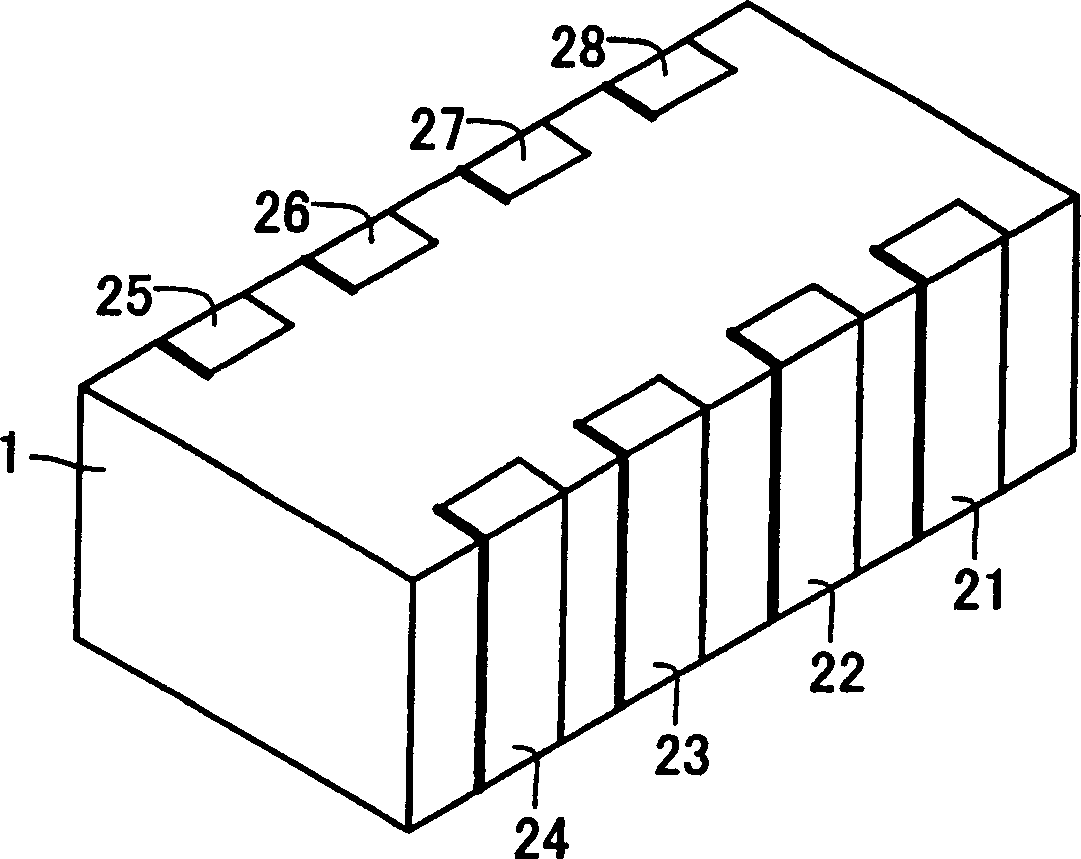
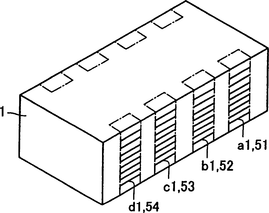
[0060] The laminated ceramic capacitor of Example 1 is Figure 1 to Figure 5 The present invention relates to a laminated ceramic capacitor shown in . The difference between the laminated ceramic capacitor of Comparative Example 1 and Example 1 is that it does not have dummy electrodes. The difference between Comparative Example 2 and the laminated ceramic capacitor of Example 1 is that the dummy electrodes are not exposed on the side surfaces of the ceramic main body.

[0061] incidence of delamination

Incidence of Fragmentation

Incidence of poor connections

Example 1

0.2%

0.2%

0.1%

Comparative example 1

1.0%

1.0%

1.0%

Comparative example 2

0.3%

0.3%

0.5%

[0062] Referring to Table 1, the occurrence rate of delamination, chipping and poor connection of Comparative Example 1 was 1.0%, which was very high. In Comparative Example 2, the occurrence rate of del...


PUM


Abstract

Provided is a laminated ceramic capacitor in which internal electrodes (A1-D1, A2-D2) are buried in layers at intervals in the thickness direction of a ceramic main body (1). The lead-out electrodes (a1-d1, a2-d2) lead out to the side of the ceramic body (1) to constitute a lead-out portion. One end of the dummy electrodes (51-58) is led out to the side in the layer provided with the internal electrodes (A1-D1, A2-D2), and constitutes a lead-out portion. The lead-out portions of the extraction electrodes ( a1 to d1 , a2 to d2 ) of each layer overlap with the lead-out portions of the dummy electrodes ( 51 to 58 ) belonging to other layers in the thickness direction.

Description

technical field [0001] This invention relates to laminated ceramic capacitors. Background technique [0002] As a laminated ceramic capacitor, for example, a laminated ceramic capacitor having a plurality of terminal pairs is known. A laminated ceramic capacitor having a plurality of terminal pairs is used as a decoupling element of a CPU (central processing unit, ie, a central processing unit) of a personal computer, and the like. For example, Patent Document 1 (Japanese Unexamined Patent Publication No. 2002-184647) discloses an internal electrode pattern of an 8-terminal laminated ceramic capacitor and a method of manufacturing the same. [0003] In addition, Patent Document 2 (Japanese Unexamined Patent Application Publication No. 2003-31435) discloses an 8-terminal laminated ceramic capacitor in which a filling layer (dummy electrode) is provided on a portion where no lead-out electrode is provided in order to prevent sinking of the ceramic dielectric layer. . [000...

Claims


Application Information

Patent Timeline
Patent Type & Authority Applications(China)
IPC IPC(8): H01G4/12H01G4/005H01G4/228H01G4/30H01G4/38
CPCH01G4/005H01G4/30
Inventor 安彦泰介增田淳富樫正明
Owner TDK CORP
Learn More