
Inverter device

一种逆变器、控制器的技术,应用在逆变器装置领域,能够解决二次电流困难等问题,达到减轻负荷、抑制温度上升、扩大阀开度的效果

Inactive Publication Date: 2005-08-17
SANYO ELECTRIC CO LTD
View PDF0 Cites 4 Cited by
  • Summary
  • Abstract
  • Description
  • Claims
  • Application Information

AI Technical Summary

Problems solved by technology

If there is an error in these numbers, it will make it difficult to correctly estimate the secondary current

Method used


Image

  • Inverter device
  • Inverter device
  • Inverter device

Examples


Embodiment 1

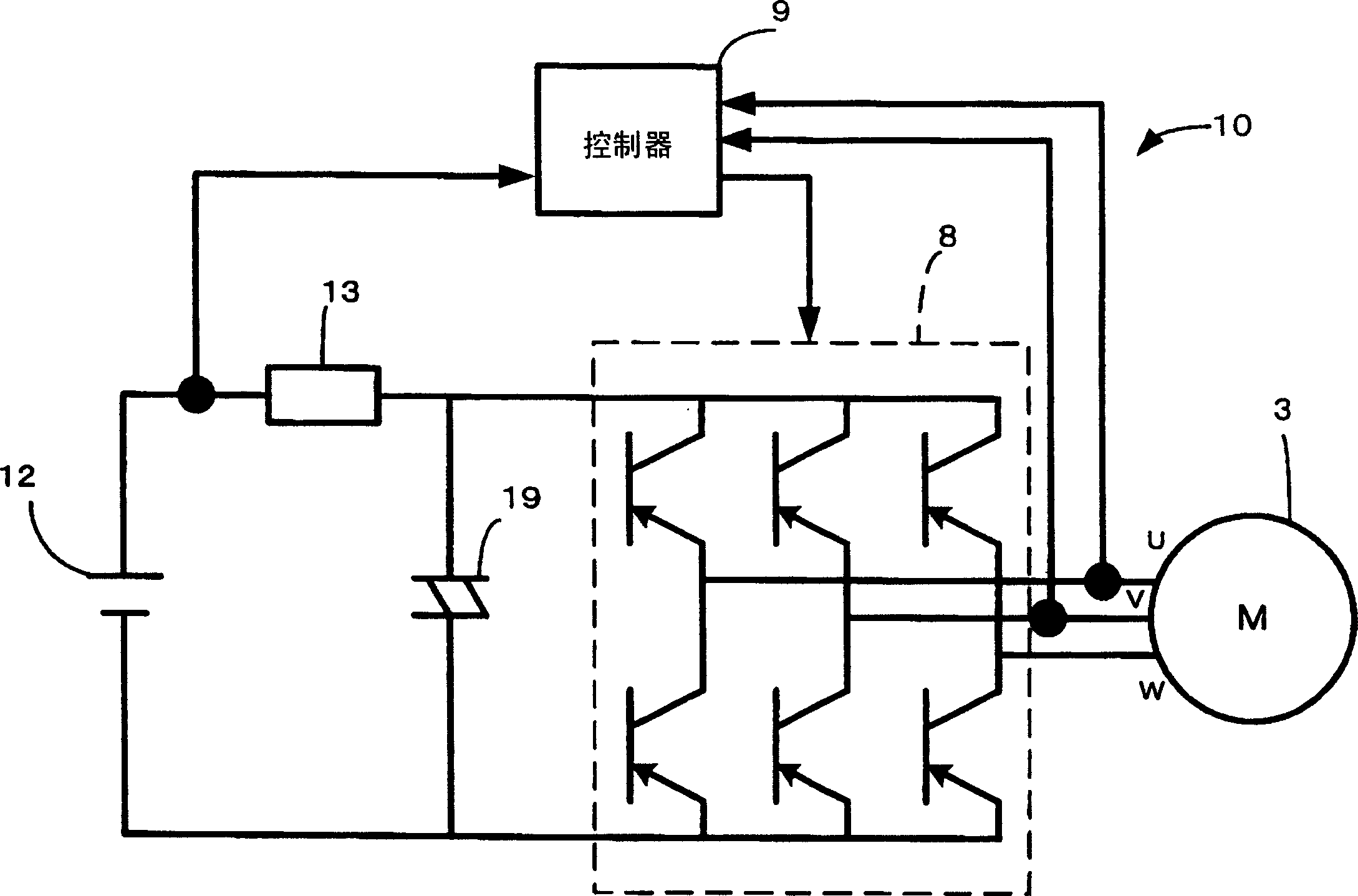
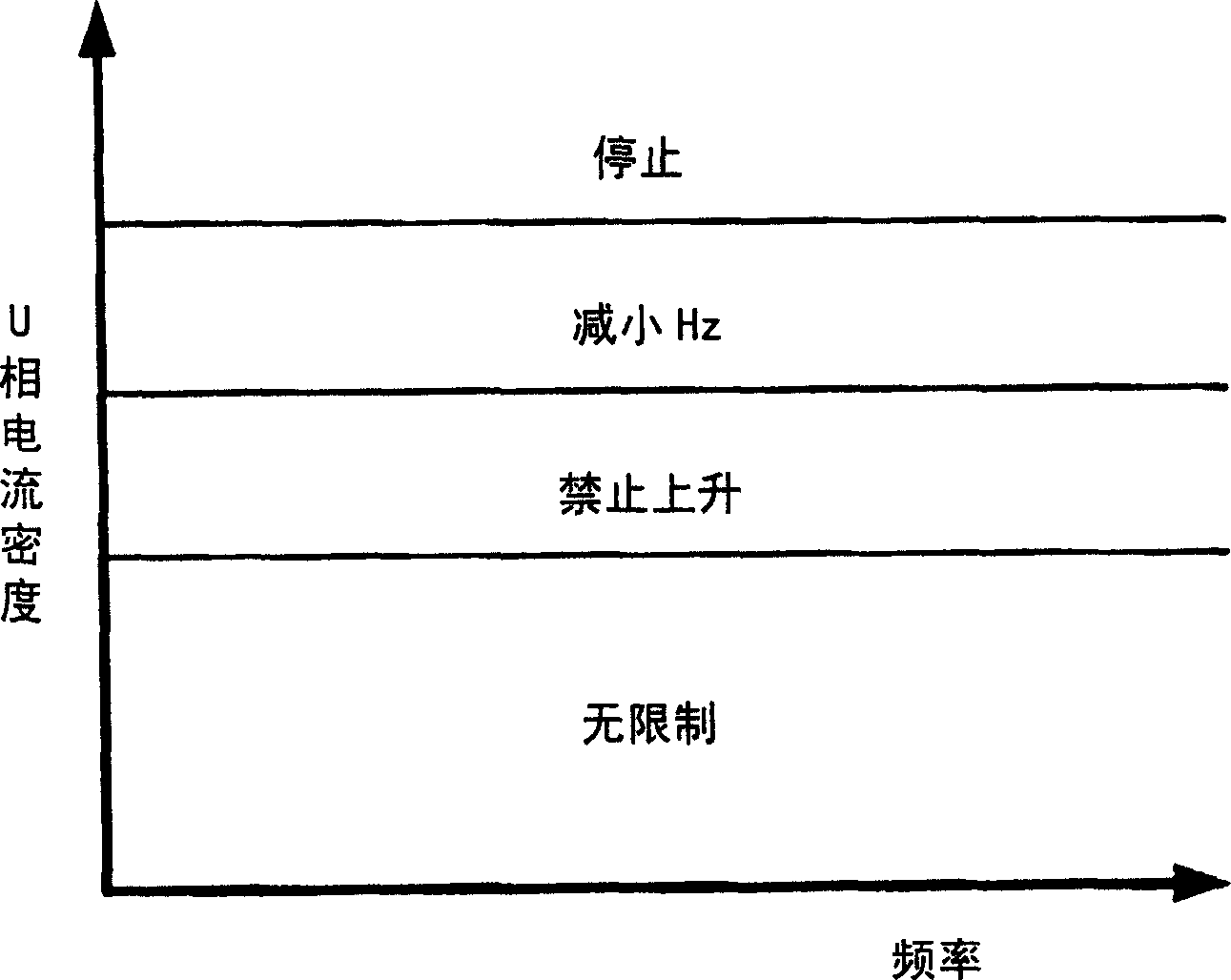
[0037] The controller 9 calculates the U-phase current density (divided by the current value by the coil cross-sectional area) flowing through the coil of the motor 3 from the secondary current (Iu) used for vector control. Next, when the U-phase current density is equal to or less than a predetermined first upper limit, the electric motor 3 is operated at a required frequency determined by the vehicle interior temperature and the set temperature (no limitation). Next, when the U-phase current density rises from the first upper limit value, the operation frequency of the electric motor 3 is restricted from being raised regardless of the required frequency.

[0038] Then, when the U-phase current density rises higher than the second upper limit higher than the first upper limit, the operating frequency of the motor 3 is lowered lower than the current frequency regardless of the required frequency. Then, finally, the motor 3 is stopped when the current density rises to a third u...

Embodiment 2

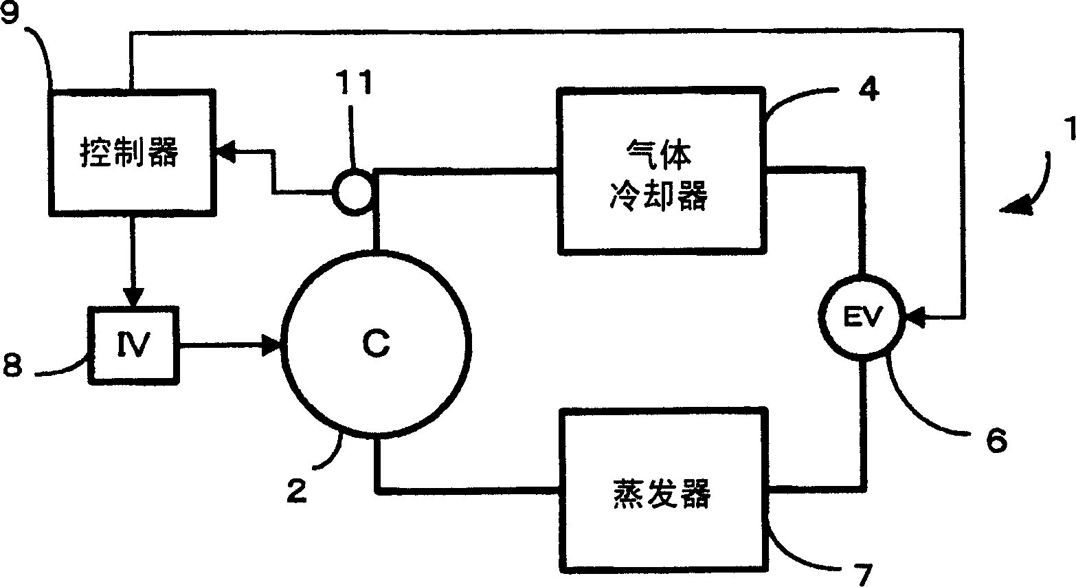
[0042] Next, another embodiment of the protection operation performed by the controller 9 will be described. Also in this case, the controller 9 calculates the U-phase current density flowing through the coil of the motor 3 from the secondary current (Iu) for vector control. Next, when the U-phase current density is equal to or less than a predetermined upper limit, the valve opening of the expansion valve 6 is adjusted to a value determined by the interior temperature, the set temperature, and the temperature of each part in the coolant circuit. Required expansion valve opening.

[0043] Next, when the U-phase current density increases from the first upper limit value, the valve opening of the expansion valve 6 is expanded in predetermined steps regardless of the expansion valve opening. In this way, the controller 9 calculates the current density flowing through the coil of the motor 3 from the secondary current flowing through the motor 3. When the current density rises, i...


PUM


Abstract

An object is to provide an inverter device capable of realizing exact protection of the winding of a motor. An inverter device for generating a pseudo alternating current by switching a direct current to drive a motor, comprises a controller that executes vector control on the basis of a secondary current applied to the motor. The controller calculates a current density from the secondary current to execute a predetermined protection operation on the basis of the calculated current density. The controller imposes a restriction on the operation frequency of the motor on the basis of the current density.

Description

technical field [0001] The present invention relates to an inverter device that converts a DC current to generate an AC current to drive a motor. Background technique [0002] Conventionally, for example, in vehicle air conditioners, the engine-driven compressor is used to circulate the coolant through the coolant circuit to cool the cabin. Vehicles using electric motors, such as cars and hybrid cars, are widely developed. In this type of automobile, since the electric power is supplied from the battery to the spindle motor to run the vehicle, the air conditioner also uses a battery-driven electric compressor. [0003] In this case, the DC current from the battery is actually converted into a three-phase analog AC current by an inverter equipped with multiple switching element groups, and applied to the motor of the electric compressor to drive the compressor, but because if the motor If a large current flows through the coil, it will be damaged, so it must be protected. ...

Claims


Application Information

Patent Timeline
Patent Type & Authority Applications(China)
IPC IPC(8): B60L3/00H02P21/00H02P27/04H02P27/06
CPCH02M1/32H02M7/53871H02P27/06F25B2600/021H02M2007/53876H02M7/53876
Inventor 久保守野岛健二
Owner SANYO ELECTRIC CO LTD
Learn More