Lower limb protecting air bag

a technology for protecting the lower limb and air bags, which is applied in the direction of vehicular safety arrangements, pedestrian/occupant safety arrangements, vehicle components, etc., can solve the problems of difficult to restrict the two right and left end sides, and it is not easy to manufacture air bags, so as to prevent the volume of air bags from increasing

Active Publication Date: 2016-03-10
TOYODA GOSEI CO LTD
View PDF6 Cites 24 Cited by
  • Summary
  • Abstract
  • Description
  • Claims
  • Application Information

AI Technical Summary

Benefits of technology

[0020]Thus, in the thus structured lower limb protecting air bag as well, while using a simple structure, in inflation completion, the end of the end side inflation part disposed at least on one of the two horizontal-direction ends of the main inflation part can be properly directed backward.
[0021]Also, in the above structured lower limb protecting air bag as well, since the bent parts are constituted of seam parts formed by superimposing and connecting together the front side wall and back side wall, even in a structure capable of covering the front of the lower limbs of the occupant in addition to the lateral sides thereof, the volume of the air bag can be prevented from increasing, thereby enabling use of a compact inflator having a small gas discharge amount. This can prevent the apparatus itself from increasing in size, thereby enabling smooth mounting of the apparatus in a narrow mounting space.
[0022]Further, in the above structured lower limb protecting air bag, since the two end side inflation parts are arranged on the two right and left sides of the main body inflation part, in both of vehicle oblique collisions from left front and from right front, the lower limbs of the occupant can be properly protected.

Problems solved by technology

However, in the lower limb protecting air bags of JP-A-H05-208653 and JP-A-2008-265660, the peripheral edges of a base fabric for forming the air bag must be connected together three-dimensionally, and thus it is not easy to manufacture the air bag.
Also, in the lower limb protecting air bag of the JP-A-2008-126974, since the outer shape of the air bag is restricted such that, the two right and left end sides of the air bag in inflation completion are directed backward by the tether disposed within the air bag in inflation completion, it is difficult to restrict the two right and left end sides so as to direct backward greatly.

Method used


Image

  • Lower limb protecting air bag
  • Lower limb protecting air bag
  • Lower limb protecting air bag

Examples


first embodiment

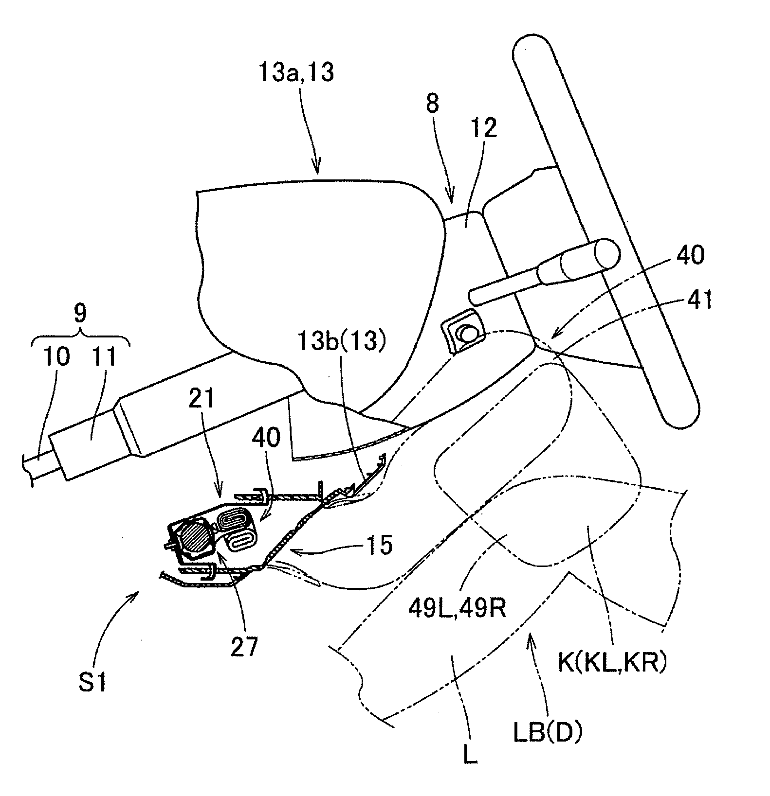
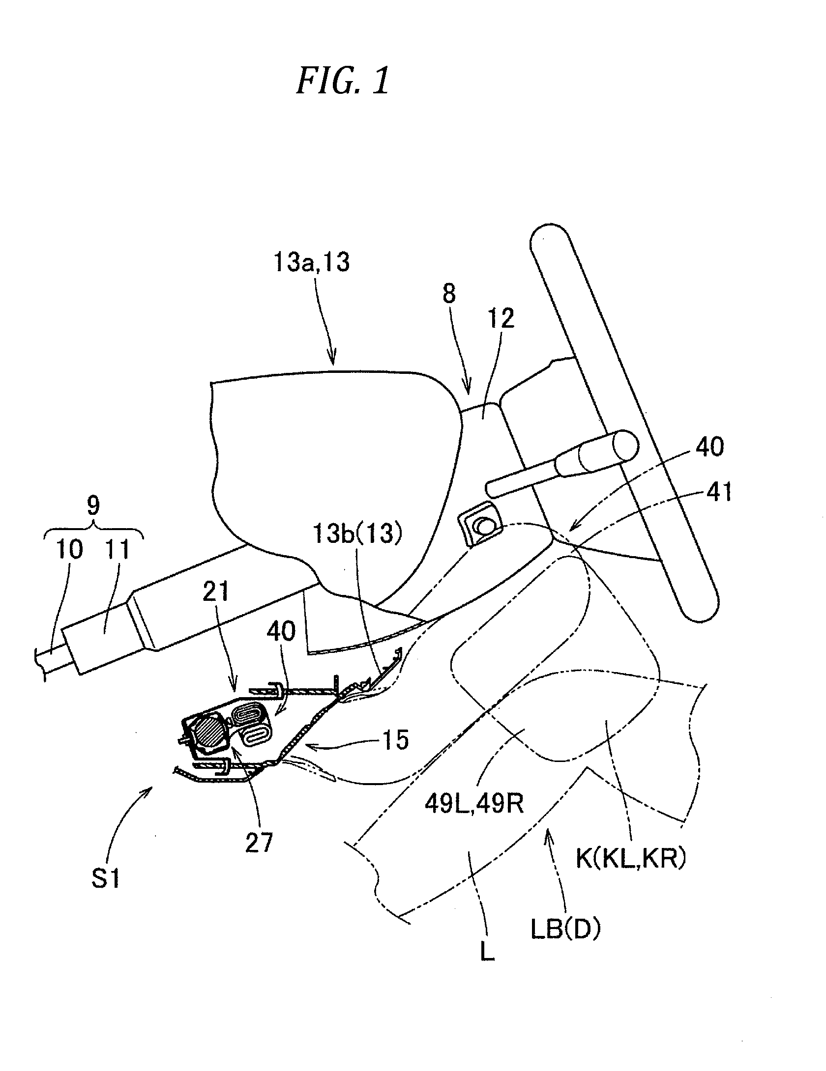
[0067]Therefore, in the air bag 40 of the first embodiment, while using a simple structure, in inflation completion, the tip ends 49a of the end side inflation parts 49L, 49R disposed on the two left and right end sides can be properly directed backward.

[0068]Of course, in the air bag 40 of the first embodiment, in a front collision, the lower limbs LB of the forward moving driver D can be properly protected by the lower limb protection portion 47.

[0069]Also, in the air bag 40 of the first embodiment, since the bending parts 51L, 51R are constituted of the seam parts 52L, 52R formed by superimposing and connecting together the front side wall 41a and back side wall 41b, even when the air bag 40 is structured to be able to cover the lateral sides of the lower limbs LB of the driver D in addition to the front side thereof, the volume of the air bag 40 can be prevented against increase, thereby enabling use of a compact inflator 27 having a small discharge quantity of gas. This can pre...

second embodiment

[0072]Next, description is given of an air bag 65 according to the invention. The air bag 65, as shown in FIGS. 11 and 13, includes a bag main body 66 inflatable when receiving inflation gas therein and an internal tether 83 disposed within the bag main body 66.

[0073]The bag main body 66 is structured such that, in inflation completion, it has a substantially rectangular plate-like shape and can protect the driver D seated in the driver seat from the left and right shins L to knees K (KL, KR). Also, the bag main body 66, as shown in FIG. 12, provides a bag-like shape formed by connecting together the peripheral edges of a back side wall 66b to be disposed on the steering column 8 side in inflation completion and a front side wall 66a to be disposed on the driver D side in inflation completion, while the two walls are substantially the same in the outer shape. That is, a main body inflation part 67 and end side inflation parts 74L, 74R (which are described later) of the bag main body...


PUM


Abstract

A lower limb protecting air bag includes: a main body inflation part; an end side inflation part; a bending part configured to bend the end side inflation part to project backward from the main body inflation part in inflation completion; and a connecting element configured to connect together the end side inflation part and the main body inflation part so that the bent state of the end side inflation part in inflation completion is maintained, wherein: the main body inflation part and the end side inflation part are configured to inflate substantially in a plate shape to separate a front side wall disposed on the back side and a back side wall disposed on the front side when the air bag is developed flat; and the bending part includes a seam part formed by superimposing and connecting together the front side wall and the back side wall.

Description

CROSS-REFERENCE TO RELATED APPLICATION(S)[0001]This application is based upon and claims the benefit of priority from Japanese Patent Application No. 2014-182699, filed on Sep. 8, 2014, the entire contents of which are incorporated herein by reference.BACKGROUND[0002]1. Field of the Invention[0003]The invention relates to a lower limb protecting air bag which is folded and stored in front of an occupant seated in a seat and, when inflation gas is supplied therein, is inflated to cover the front of the lower limbs of the occupant.[0004]2. Description of the Related Art[0005]Conventionally, there are known a lower limb protecting air bag structured to inflate with its two right and left sides projected backward (for example, see JP-A-H05-208653 and JP-A-2008-126974), and an air bag structured to inflate with the two right and left sides and horizontal-direction central side thereof projected backward (for example, see JP-A-2008-265660).[0006]In the lower limb protecting air bag disclo...

Claims


Application Information

Patent Timeline
Patent Type & Authority Applications(United States)
IPC IPC(8): B60R21/233B60R21/206
CPCB60R21/233B60R2021/23316B60R2021/23169B60R21/206B60R2021/23386
Inventor KOMATSU, TAKANORIANDO, TAKESHIIMAEDA, HIROKIOGATA, TETSUYA
Owner TOYODA GOSEI CO LTD
Why Eureka
Try Eureka