Retina prostration apparatus
A retina and rod technology, applied in the field of medical devices, can solve the problems of easy damage to the retina, poor effect, low efficiency, etc., and achieve the effect of improving the operation effect, saving the operation time, and improving the operation efficiency.
- Summary
- Abstract
- Description
- Claims
- Application Information
AI Technical Summary
Problems solved by technology
Method used
Image
Examples
Embodiment 1
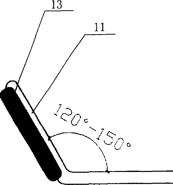
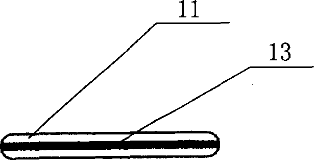
[0029] The structure of the retinal applanator is as follows: figure 1 As shown, it consists of a working head 1, a rod body 2 and a handle 3. The rod body 2 is a metal rod made of stainless steel with a diameter of 0.4mm and a length of 40mm. The working head 1 and the rod body form an angle of 120 degrees. Its angle can be fine-tuned with blood vessel forceps, and the base body 11 of this working head is the continuous body with the same diameter of rod body 2 (such as figure 2 As shown), its length is 2mm, and a very thin silicone sheet 13 is inlaid on the downward side of the substrate 11 as a soft touch working element. Its shape is similar to a brush, and the thickness of the silicone sheet 13 is 0.1mm. The length protruding from the substrate is 0.3mm (such as image 3 , 4 shown). The total length of the retina applanator is about 110mm.
[0030] When using this retina applanator, adjust the angle of the working head with vascular forceps according to different mas...
Embodiment 2
[0032] The structure of the retinal applanator is shown in Figure 5. It consists of a working head 1, a rod body 2 and a handle 3. The rod body 2 is a metal rod made of stainless steel with a diameter of 0.8 mm and a length of 30 mm. The working head 1 It forms an angle of 120 degrees with the rod body, and the angle can be adjusted by vascular forceps during use. The soft touch working element of the working head is a silicone tube 12 set on the base body, and the thickness of the tube wall is 0.2mm (such as Figure 7 shown). The base of the working head can be the core portion 11 of the reduced diameter extending from the front end of the rod body, with a diameter of about 0.4mm (such as Figure 8 shown), after the silicone tube 12 is inserted into the matrix, the outer diameter of the entire working head is equal to the outer diameter of the rod body (such as Figure 6 shown). The total length of the retina applanator is about 130mm.
Embodiment 3
[0034] The structure of the retinal applanator is shown in Figure 9. It consists of a working head 1, a rod body 2 and a handle 3. Its structure is basically the same as that of Embodiment 2. The difference lies in the silicone rubber used as the soft touch working element of the working head. Pipe 12 is only enclosed within a section of working head front (as Figure 10 shown). The silicone tube 12 of the working head and the substrate 11 are as Figure 11 , 12 shown.
PUM
 Abstract
Description
Claims
Application Information
 - R&D Engineer
- R&D Manager
- IP Professional
- Industry Leading Data Capabilities
- Powerful AI technology
- Patent DNA Extraction
Browse by: Latest US Patents, China's latest patents, Technical Efficacy Thesaurus, Application Domain, Technology Topic, Popular Technical Reports.
© 2024 PatSnap. All rights reserved.Legal|Privacy policy|Modern Slavery Act Transparency Statement|Sitemap|About US| Contact US: help@patsnap.com


