
Recycle for supercritical carbon dioxide

A carbon dioxide and catalytic oxidation technology, applied in liquefaction, inorganic chemistry, carbon compounds, etc., can solve the problems that economic feasibility cannot be completely relied on, and no system or method is pointed out, so as to reduce cost and complexity, reduce production cost, and reduce cost effect

Inactive Publication Date: 2005-04-06
PRAXAIR TECH INC
View PDF0 Cites 6 Cited by
  • Summary
  • Abstract
  • Description
  • Claims
  • Application Information

AI Technical Summary

Problems solved by technology

Moreover, if the supercritical carbon dioxide process is widely used in the semiconductor industry, the consumption cannot be economically viable to rely entirely on the available carbon dioxide
[0006] However, the prior art does not point to a system or method that can solve these problems

Method used


Image

  • Recycle for supercritical carbon dioxide
  • Recycle for supercritical carbon dioxide
  • Recycle for supercritical carbon dioxide

Examples


Embodiment

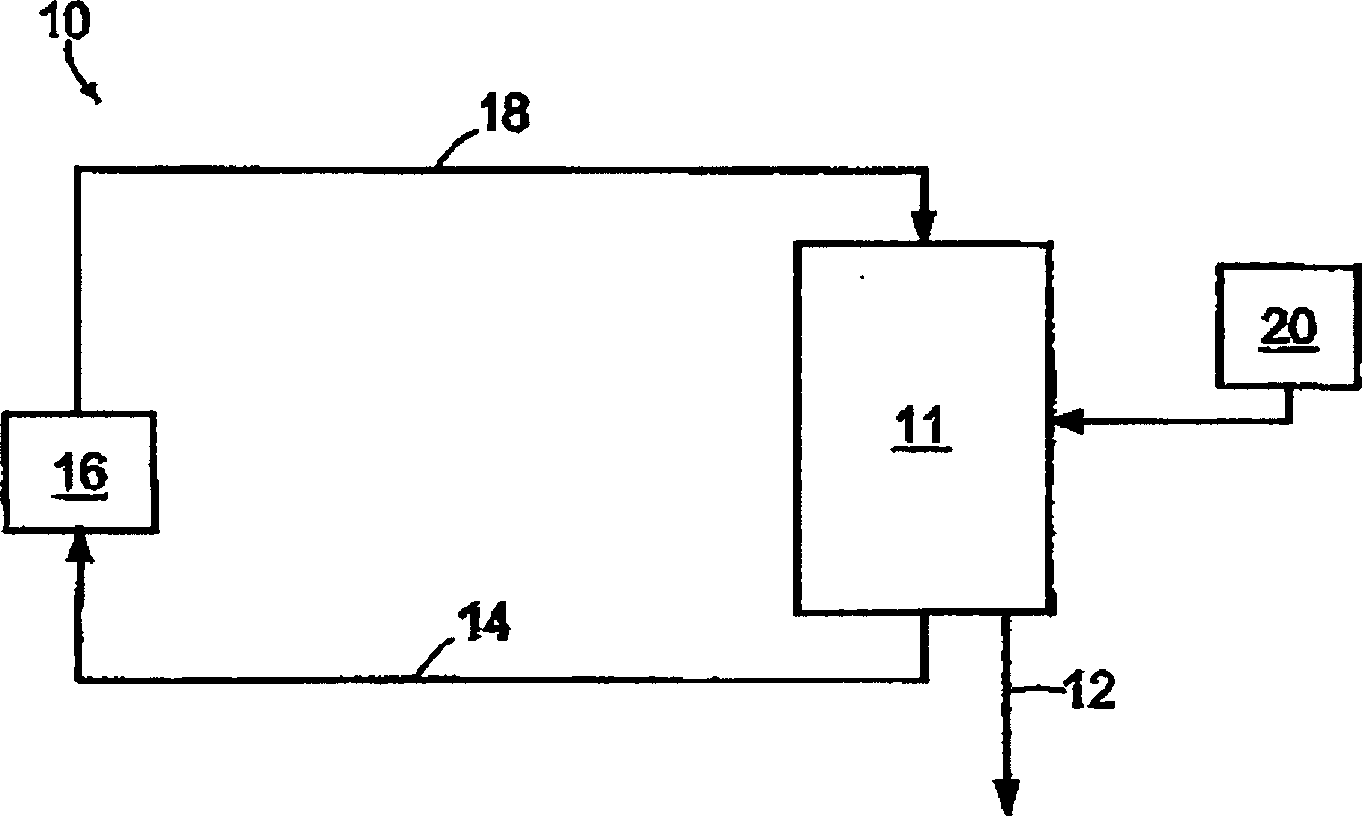
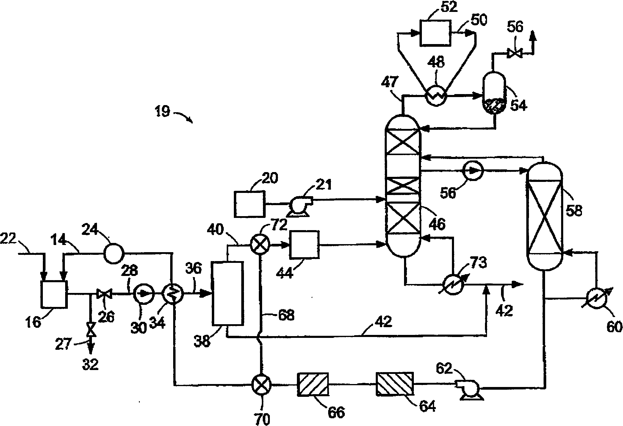
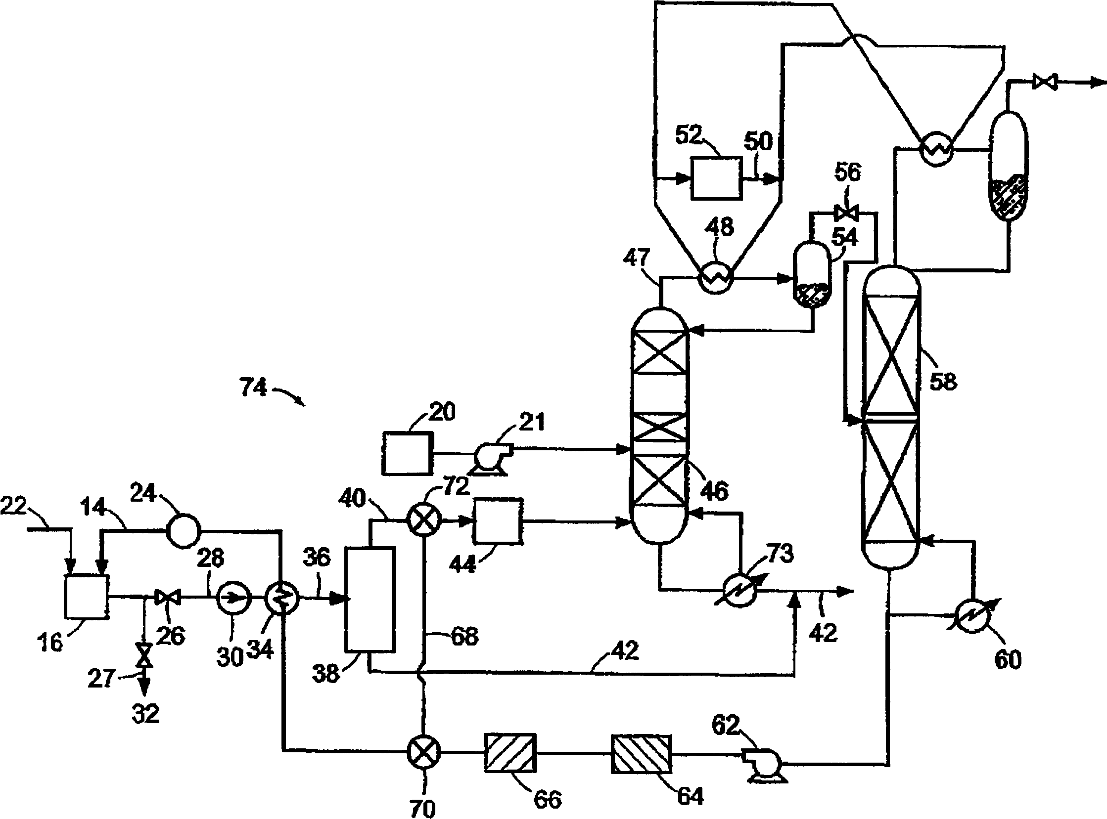
[0048] Table 1 gives the corresponding Figure 4 Values ​​for the flow conditions and compositions of the individual material streams of the process shown. In this example, the expanded stream undergoes phase separation at reduced temperature in vessel 38 and is warmed to ambient temperature before entering first distillation column 46 . Impurities considered should include oxygen, nitrogen, methane (introduced with the added liquid), water, hexane, propylene carbonate, acetone and ethyl acetate. For these impurities, reactor 44 and heat exchanger 80 between columns 46 and 58 are not required. Furthermore, condensers 48 and 82 are preferably operated in the same unit.

[0049] The energy flows are listed in Table 2. The cooling power can be estimated based on the usage of the ammonia refrigeration loop. It can be assumed that this loop can power the reboilers 41 and 44 and that the cold water for condensing the high pressure ammonia vapor in the refrigeration loop is avail...


PUM

PropertyMeasurementUnit
boiling pointaaaaaaaaaa

Abstract

A method and a system for supplying a carbon dioxide fluid feed from a carbon dioxide purifying means to one or more applications. The feed is combined with contaminants at the applications to form an effluent, and at least one effluent is returned to the purifying means for recycling the carbon dioxide. Carbon dioxide from a carbon dioxide source is combined with the carbon dioxide of the system so that the purity of the carbon dioxide from the source is upgraded prior to the applications.

Description

[0001] related application [0002] This application claims priority to US Provisional Application No. 60 / 330,150, filed October 17, 2001, the entire contents of which are hereby incorporated by reference. This application also claims U.S. Provisional Application Nos. 60 / 330,203, filed October 17, 2001, and U.S. Provisional Application Nos. 60 / 350,688, filed January 22, 2002, and 60 / 358,065, filed February 19, 2002. Priority, all of these applications are hereby incorporated by reference in their entirety. Background of the invention [0003] The fabrication of integrated circuits typically involves a large number of discrete steps performed on a wafer. Typical steps include deposition or growth of thin films, patterning and etching of wiring on the wafer using photolithography. These steps are performed multiple times to build the desired circuit. Other process steps may include ion implantation, chemical or mechanical planarization and percolation. To perform these steps...

Claims


Application Information

Patent Timeline
Patent Type & Authority Applications(China)
IPC IPC(8): B01D19/00B01D3/14B01D15/00B01D53/04B01J3/00B08B7/00C01B32/50C02F1/04C02F1/20C02F1/28F25J3/02F25J3/08G01N1/22G01N1/40G01N1/42G01N15/04G01N15/06H01L21/027H01L21/304
CPCY02C10/12B01D2256/26B01D15/00B01D3/14F25J2220/80B08B7/0021G01N15/04B01D3/146G01N15/06F25J3/08F25J2220/82G01N1/42B01D2256/22F25J2245/02G01N1/2202B01D53/04F25J2260/80F25J2200/30F25J2220/84G01N2001/2282F25J3/0266F25J2290/50G01N2001/2238F25J2200/02F25J2200/78F25J2270/90F25J2200/74F25J2205/04G01N1/40F25J2215/80F25J2235/80C01B31/20F25J2210/80C01B32/50Y02P20/54Y02P70/10F25J2205/30Y02C20/40Y02P20/151
Inventor H·E·霍瓦德J·F·比林哈姆
Owner PRAXAIR TECH INC
Learn More