Method for measuring retaining stress double-refraction value of stress deflection fibre-optical
A technology of stress birefringence and polarization maintaining optical fiber, which is applied in the direction of testing optical performance, electromagnetic wave transmission system, electrical components, etc.
- Summary
- Abstract
- Description
- Claims
- Application Information
AI Technical Summary
Problems solved by technology
Method used
Image


Examples
specific Embodiment approach 1
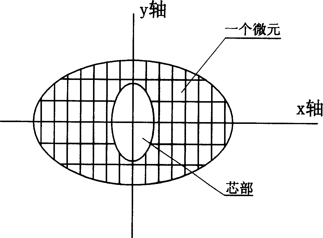
[0012] Specific implementation mode one: the following combination figure 2 This embodiment will be specifically described. The technical measure of the present invention comprises the following steps: (1) measurement of dopant element concentration: take the polarization-maintaining optical fiber preform as raw material, adopt crystal cutting knife to transversely cut it into discs with a thickness of 2mm-5mm, the release of stress makes Many microcracks are produced in the stress area of the wafer; then take out the samples of the stress area and the core area respectively, measure the content of the B element in the stress area sample, and measure the content of the Ge element in the core area sample; determine the stress at the same time as the doping element concentration measurement The geometry of the region and the core region: Take the polarization-maintaining fiber, cut it with a fiber cutter to cut a few small pieces of optical fiber as samples, keep the cut end ...
specific Embodiment approach 2
[0043] Embodiment 2: The difference between this embodiment and Embodiment 1 is that in step (1), the content of B element in the stress region is measured by volumetric method, and the content of Ge element in the core region is analyzed by atomic fluorescence spectrometry. When determining the geometry of the stress region and the core region, a total of 5-10 small pieces of optical fiber were cut to make samples. In order to prevent the foaming and expansion of the glue, keep the temperature below 20°C. In step (2), use Paintshop, Photoshop, Microsoft Photo Editor or Windows drawing tool to clean up the impurities in the backscattered atomic contrast image. Other steps are the same as the first embodiment.
specific Embodiment approach 3
[0044] Embodiment 3: The difference between this embodiment and Embodiment 1 is that in step (1), the end face of the optical fiber segment is sprayed with carbon, copper, gold or platinum as a conductive film. The contents of B and Ge were measured by ICP-AES method. Other steps are the same as those in Embodiment 1.
PUM
| Property | Measurement | Unit |
|---|---|---|
| Thickness | aaaaa | aaaaa |
| Thermal expansion coefficient | aaaaa | aaaaa |
Abstract
Description
Claims
Application Information
 - R&D
- Intellectual Property
- Life Sciences
- Materials
- Tech Scout
- Unparalleled Data Quality
- Higher Quality Content
- 60% Fewer Hallucinations
Browse by: Latest US Patents, China's latest patents, Technical Efficacy Thesaurus, Application Domain, Technology Topic, Popular Technical Reports.
© 2025 PatSnap. All rights reserved.Legal|Privacy policy|Modern Slavery Act Transparency Statement|Sitemap|About US| Contact US: help@patsnap.com