
In cylinder fuel oil jet type IC engine

A technology of internal injection and internal combustion engine, which is applied to internal combustion piston engine, combustion engine, and the fuel is brought into the engine through high-pressure gas. Good performance, suppression of rarefaction, and improvement of ignition efficiency

Inactive Publication Date: 2005-03-09
HONDA MOTOR CO LTD +1
View PDF1 Cites 9 Cited by
  • Summary
  • Abstract
  • Description
  • Claims
  • Application Information

AI Technical Summary

Problems solved by technology

[0010] Since the ignition part of the spark plug is located at the edge of the chamber, there is a risk that the ignition will become unstable if it is ignited at the edge of the mixture layer formed in the chamber.
[0011] In addition, if the spark plug in an inclined posture is separated from the central axis of the chamber, and only the ignition part at the tip is located in the chamber, the chamber itself will become larger, and improvement in fuel efficiency cannot be expected.

Method used


Image

  • In cylinder fuel oil jet type IC engine
  • In cylinder fuel oil jet type IC engine
  • In cylinder fuel oil jet type IC engine

Examples


Embodiment Construction

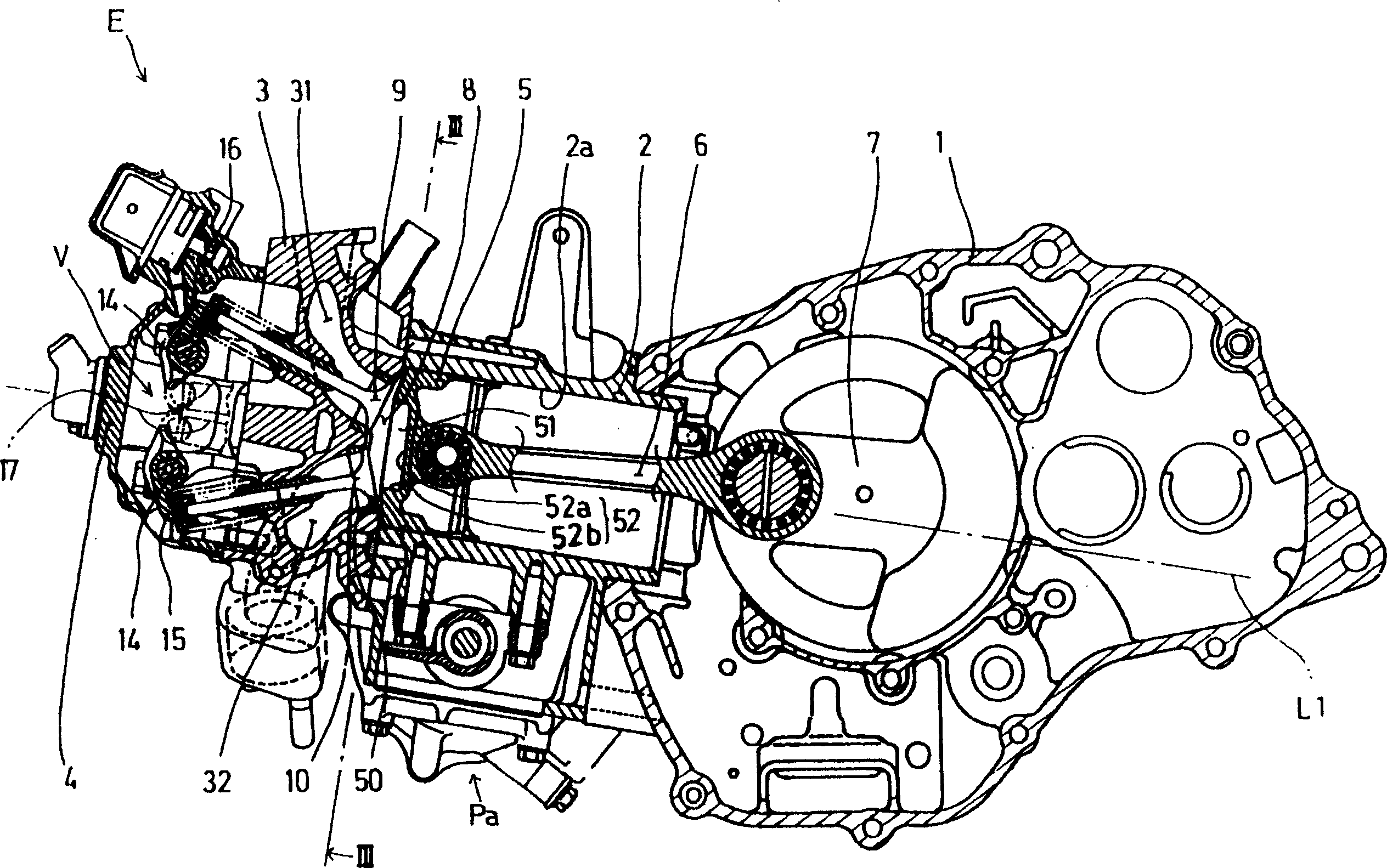
[0028] Hereinafter, an embodiment of the present invention is based on Figure 1 to Figure 5 Be explained.

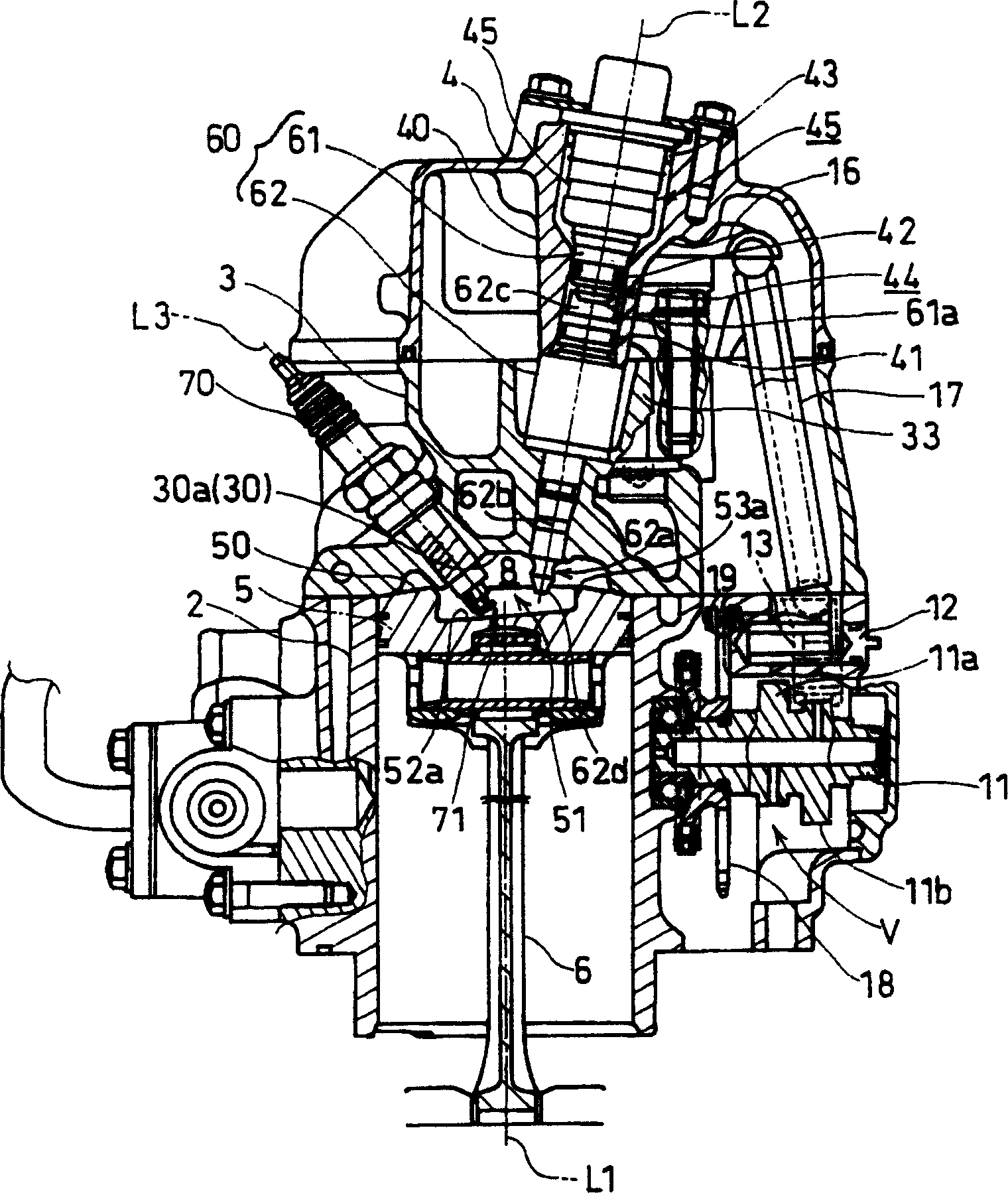
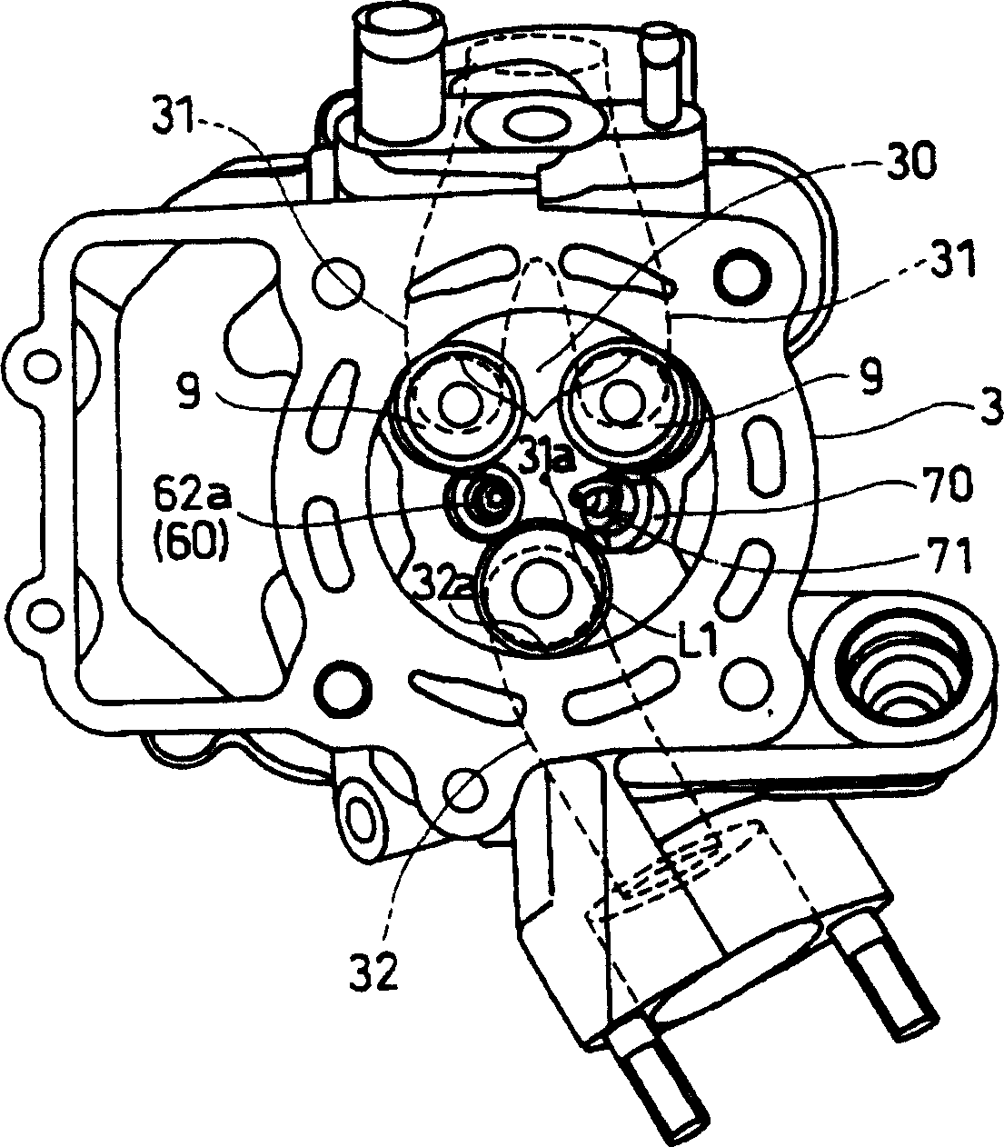
[0029] refer to figure 1 , figure 2 , the fuel injection type internal combustion engine E applied in the cylinder of the present invention is a spark ignition type 4-stroke single-cylinder internal combustion engine, having a cylinder 2 coupled to a crankcase 1 that rotatably supports a crankshaft 7, and a cylinder 2 coupled to the upper end of the cylinder 2 A cylinder head 3, and a cylinder head cover 4 coupled to the upper end of the cylinder head 3.

[0030] A piston 5 reciprocally fitted in a cylinder bore 2 a of the cylinder 2 rotatably drives a crankshaft 7 via a connecting rod 6 .

[0031] And, the internal combustion engine E such as figure 1 As shown, the cylinder 2 located in front of the vehicle with respect to the crankshaft 7 is mounted on the motorcycle in a state inclined slightly upward of the vehicle.

[0032] Between the cylinder 2 and the cyli...


PUM


Abstract

PROBLEM TO BE SOLVED: To provide a cylinder injection internal combustion engine with excellent ignitability for improving combustion efficiency and improving fuel consumption without enlarging a cavity, by separating a tip firing part of an ignition plug from a jet flow of a fuel injection valve and bringing the tip firing part close to a center axis of the cavity. ŽSOLUTION: In the cylinder injection internal combustion engine, a combustion chamber 8 is formed between a piston 5 in which the cavity 51 is formed in a top surface thereof and a cylinder head 3, and a lower wall surface of the cylinder head 3 is a ceiling surface of the combustion chamber 8. A plurality of intake and exhaust valves, the fuel injection valve 60, an ignition plug 70 are disposed to face the combustion chamber 8. The ignition plug 70 is inserted from a side surface of the cylinder head 3 toward the combustion chamber 8, and the tip firing part 71 thereof is inclined with respect to the cylinder axis L1 and approximated to the center axis L1. The fuel injection valve 60 is inserted from an upper surface of the cylinder head 3 toward the combustion chamber 8 and inclined on a side approximately opposite to the ignition plug 70 with respect to the cylinder axis L1, and a tip nozzle 62a thereof is separated in an inclination direction from the center axis L1 of the cavity 51. Ž

Description

technical field [0001] The present invention relates to a spark ignition type in-cylinder fuel injection type internal combustion engine in which a fuel injection valve near a combustion chamber injects fuel toward a cavity formed on a top surface of a piston. Background technique [0002] In order to improve the fuel efficiency of the internal combustion engine, the fuel injection type internal combustion engine in the cylinder adopts that even if the overall air-fuel ratio in the combustion chamber becomes lean, a mixture layer with a rich air-fuel ratio can be locally formed in the cavity formed on the top surface of the piston. The layered combustion method of gas mixture layer ignition. [0003] Therefore, the fuel injection valve is configured to inject fuel into a cavity formed on the top surface of the piston facing the combustion chamber, and the spark plug can ignite in the air-fuel mixture layer formed in the cavity (for example, refer to Patent Document 1). [0...

Claims


Application Information

Patent Timeline
Patent Type & Authority Applications(China)
IPC IPC(8): F02B17/00F02B3/02F02B5/00F02B23/06F02B23/08F02B23/10F02M57/06F02M67/00F02M69/04F02P13/00
CPCY02T10/125Y02T10/12
Inventor 铃木正刚塙薰小川夏江
Owner HONDA MOTOR CO LTD
Learn More