
Plane strain measurement sensor

A technology for measuring sensors and plane strain, which is applied in the direction of mechanical solid deformation measurement and material inspection products, etc. It can solve the problems of large influence on strain data and impossibility of testing, etc., and achieve the effects of variable gauge length, improved output stability, and easy calibration

Inactive Publication Date: 2005-03-02
CHANGAN UNIV
View PDF1 Cites 14 Cited by
  • Summary
  • Abstract
  • Description
  • Claims
  • Application Information

AI Technical Summary

Problems solved by technology

The strain gauge of this structure has been tested in the laboratory and the bridge construction house. Compared with the strain gauge, the strain gauge of the double cantilever concrete structure proves that it has high sensitivity, easy calibration, small linear error, good long-term stability, It has the advantages of variable gauge length, low production cost, wide application range, strong moisture resistance, stable output signal, and convenient use. However, this strain gauge can only measure the strain in one direction on the surface of the structure. Strain in different directions, unable to test
In addition, this kind of double-cantilever concrete structure strain gauge does not have a heat insulation layer in the sensor. During the test, due to temperature changes, the spring leaf installed in the sensor is deformed due to temperature changes. The spring leaf directly feels the measured temperature. The deformation of the component under load, the strain gauge installed on the spring piece senses the deformation of the spring piece and outputs the strain signal, which has a great influence on the measured strain data

Method used


Image

  • Plane strain measurement sensor
  • Plane strain measurement sensor
  • Plane strain measurement sensor

Examples


Embodiment 1

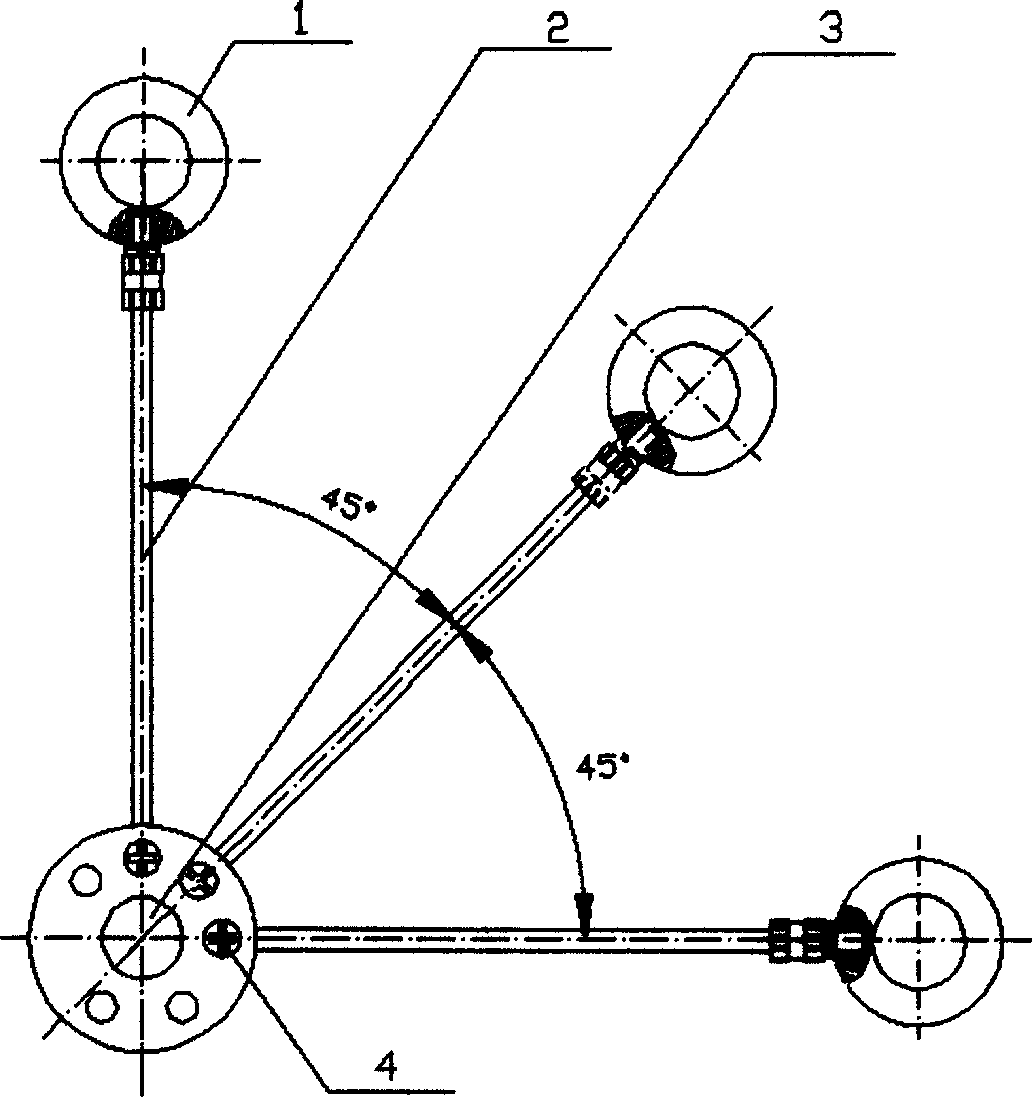
[0021] figure 1 A schematic structural diagram of an embodiment of the 45° right-angle plane strain measuring sensor of the present invention is given. exist Figure 1~6 Among them, the plane strain measurement sensor of the present invention is composed of a sensor 1, a connecting rod 2, a multidirectional support 3, and a limiting screw 4.

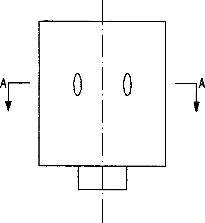
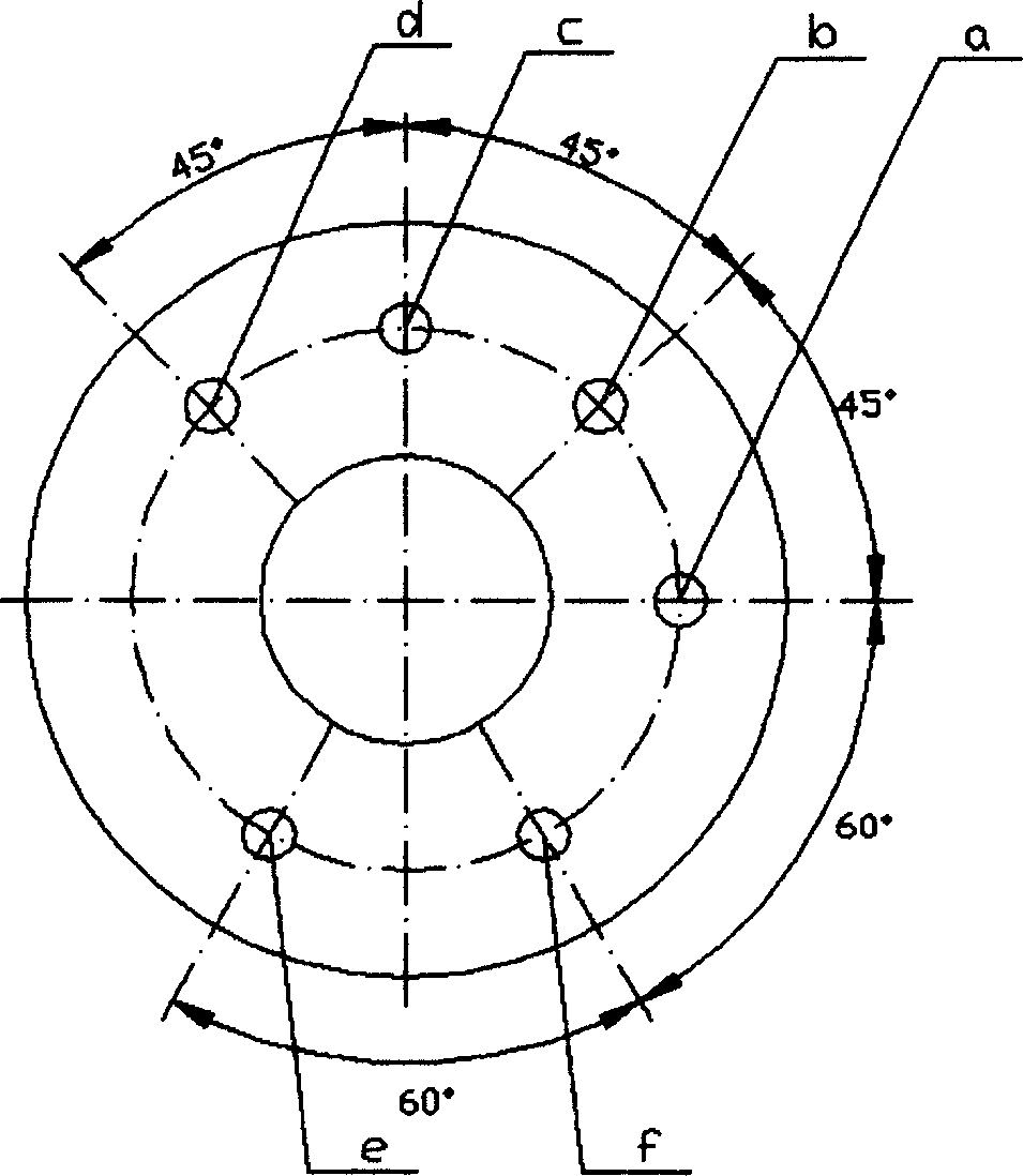
[0022] The shape of the multidirectional pillar 3 of the present embodiment is a cylinder, and a center hole is processed in the center of the multidirectional pillar 3, and a, b, c, d, e are sequentially processed in the axial direction on the upper surface of the multidirectional pillar 3 , f six screw holes can also be processed into positioning slot holes, the central angle between a screw hole and b screw hole, b screw hole and c screw hole, c screw hole and d screw hole is 45°, d screw hole The central angle between screw hole e and screw hole e is 105°, the central angle between screw hole e and screw hole f is 60°, and the cent...

Embodiment 2

[0037] exist figure 2 , 3 , 4, 7, the plane strain measurement sensor of the present embodiment is connected by multi-directional pillar 3, four connecting rods 2, four sensors 1, and limiting screw 4 into a fan-shaped plane strain measurement sensor. In the screw holes a, b, c, and d on the upper surface of the multi-directional pillar 3, limit screws 4 are installed to fix and install the four connecting rods 2 on the sides of the multi-directional pillar 3 facing a', b' in the same plane. , c', d' holes, a sensor 1 is connected to the other end of each connecting rod 2 to form a fan-shaped plane strain measurement sensor, and each sensor 1 is connected to a strain gauge through a cable. The structures of the sensor 1 and the multi-directional support 3 are the same as those of the first embodiment. The fan-shaped plane strain measurement sensor of this embodiment is suitable for measuring the strain value of the measured part of the component when the principal strain or...

Embodiment 3

[0048] exist figure 2 , 3 , 4, 8, the plane strain measuring sensor of the present embodiment is to be connected into 60 ° equiangular plane strain measuring sensor by multi-directional pillar 3, three connecting rods 2, three sensors 1, limit screw 4. In the a, e, f screw holes on the upper surface of the multi-directional pillar 3, limit screws 4 are installed to fix the three connecting rods 2 respectively on the a', e', f' in the same plane on the side of the multi-directional pillar 3. In the hole, a sensor 1 is connected to the other end of each connecting rod 2, and each sensor 1 is connected with a strain gauge through a cable to form a 60° equiangular plane strain measurement sensor. The structures of the sensor 1 and the multi-directional support 3 are the same as those of the first embodiment. The 60° equiangular plane strain measurement sensor of this embodiment is suitable for measuring the strain value of the measured part of the component when the principal s...


PUM

PropertyMeasurementUnit
Thicknessaaaaaaaaaa
Lengthaaaaaaaaaa

Abstract

A plane strain measuring sensor has the characteristics: at least two bolt holes or locating slot holes are processed in top surface axial direction of multi-direction support, radial hole processed on the same plane with lateral face radial direction is corresponding and interconnected to the bolt holes or locating slot holes of top surface, at least two connecting rods has one end separately set in radial hole of multi-direction support and another end linked separately to the sensors on the same plane but different directions. Tested in laboratory and by bridge load test, the invention is proved to have the advantages: rational design, high sensitivity, easy standardization, small linear error, excellent interference killing and dampness feature, good stability, changeable standardization, wide use, apart from these, after linking to static strainometer or dynamic strainometer, it can measure strain on the same plane but different directions of building unit such as highway bridge and railroad bridge and that of metal unit as well.

Description

technical field [0001] The invention belongs to the technical field of equipment for measuring relative displacement, and in particular relates to a plane strain measuring sensor. Background technique [0002] Strain is usually one of the main physical quantities that need to be observed in engineering quality inspection, service life evaluation, disease cause analysis, and new structural type test research of bridges and various building structures. There are two main methods used to measure building strain at present. One is the strain gauge, which is directly pasted on the detected part of the structure during use. Chip placement, wire bonding, and chip sealing are often carried out at a height of several meters or even tens of meters, which is relatively difficult, difficult to guarantee quality, and relatively low efficiency. Moreover, the measured value is greatly affected by the ambient temperature and humidity, and there are often some points. The measured value dr...

Claims


Application Information

Patent Timeline
IPC IPC(8): G01B5/30G01N33/38
Inventor 王建华胡大琳郝宪武郑勇
Owner CHANGAN UNIV
Learn More