
Axial flux motor driven anode target for x-ray tube

An X-ray tube and axial flux technology, applied in the field of X-ray tubes, can solve problems such as excessive static load and dynamic load

Inactive Publication Date: 2005-02-02
GENERAL ELECTRIC CO
View PDF0 Cites 9 Cited by
  • Summary
  • Abstract
  • Description
  • Claims
  • Application Information

AI Technical Summary

Problems solved by technology

[0004] Although specific methods have been used to minimize the thermal load on the X-ray tube bearings, problems associated with the excessive static and dynamic loads encountered by the bearings still present challenges to X-ray tube designers
The typical mass distribution of rotating parts imposes additional constraints on the design of X-ray generation systems, especially with regard to reducing weight and improving the overall compactness of the X-ray tube

Method used


Image

  • Axial flux motor driven anode target for x-ray tube
  • Axial flux motor driven anode target for x-ray tube
  • Axial flux motor driven anode target for x-ray tube

Examples


Embodiment Construction

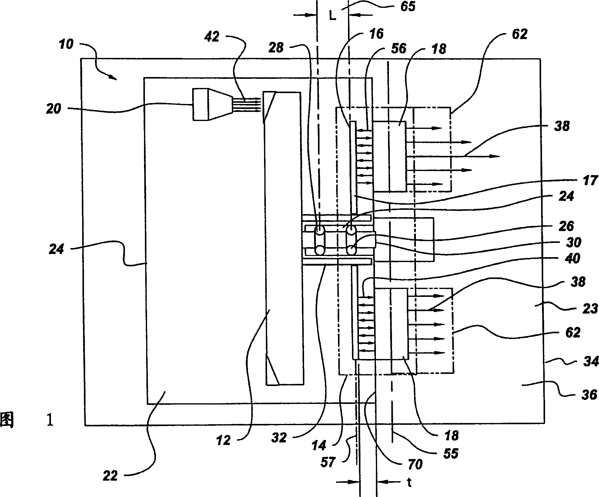
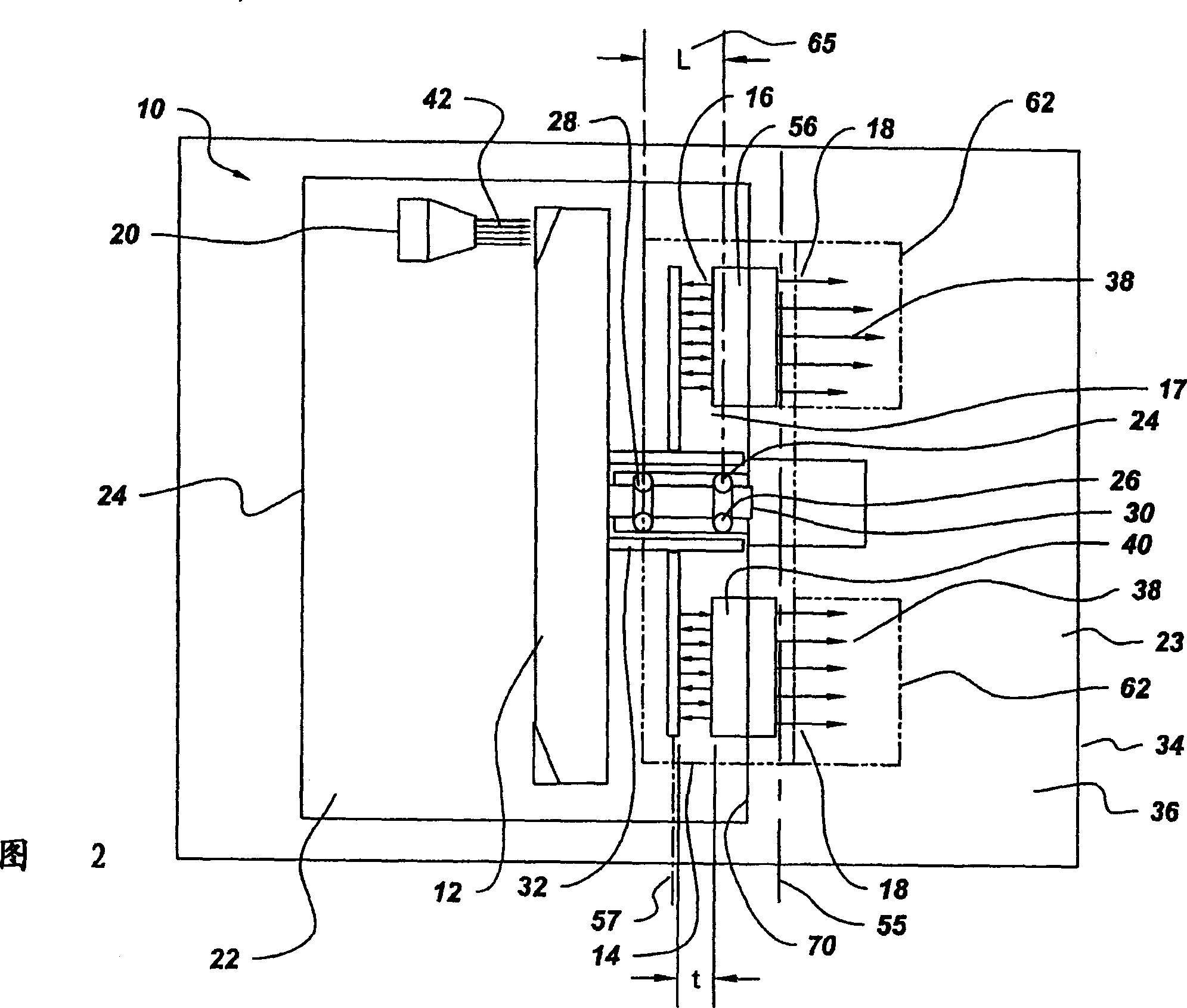
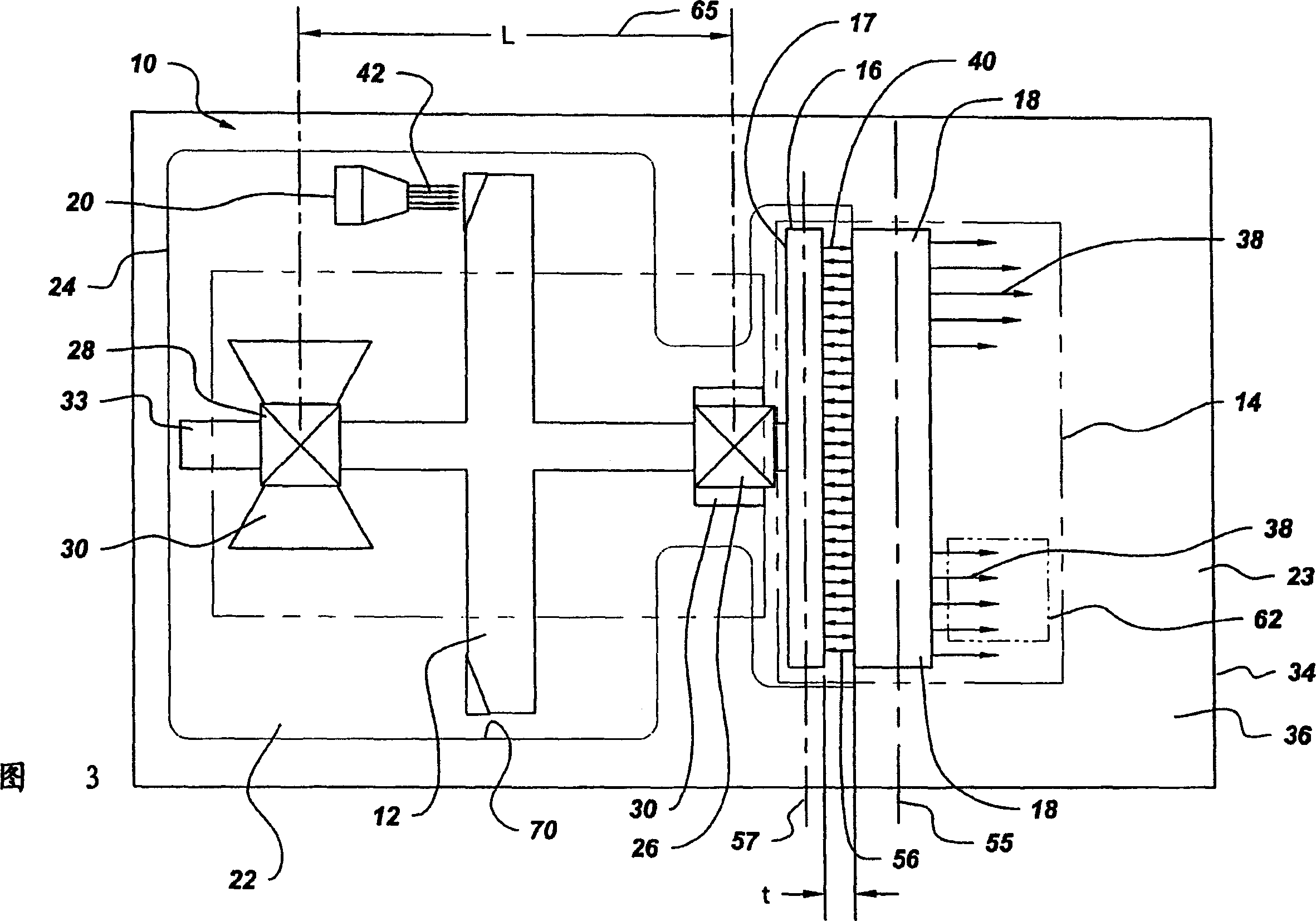
[0026] An X-ray generator, also called an X-ray tube 10 , is shown in FIGS. 1 to 6 . X-ray tube 10 includes an anode target assembly 12 . Anode target assembly 12 is typically fabricated from a relatively high atomic number metal such as tungsten or a tungsten alloy, molybdenum or rhenium, for example. A cathode filament (not shown) disposed within cathode assembly 20 is heated, thereby emitting an electron beam 42 . A potential difference, typically on the order of about 60 kilovolts to 140 kilovolts, is applied between cathode assembly 20 and anode target assembly 12 to accelerate electron beam 42 generated by cathode assembly 20 . Once accelerated, electron beam 42 impinges on anode target assembly 12 to generate electromagnetic radiation. This electromagnetic radiation is typically X-ray radiation.

[0027] A portion, typically about 1%, of the kinetic energy of the electron beam 42 is converted into x-ray radiation, while the remainder is converted into thermal energy....


PUM


Abstract

The X-ray tube(10) includes a cathode(20), rotor target assembly(12), and axial flux type motor(14) having a rotor(16) and stator(18). The stator(18) is arranged along with a lateral axial line(55) parallel to a rotor axial line(57). The rotor(16) and stator(18) are connected to the anode target assembly(12). The cathode(20) generates an electron beam(42) and makes the electron beam(42) collide on the anode target assembly(12). The vacuum housing(22) surrounds the anode target assembly(12), cathode(20), and rotor(16) to make the collision of the electron beam(42) possible.

Description

technical field [0001] This invention relates generally to an X-ray generating system, and more particularly to an X-ray tube driven by an axial flux motor. Background technique [0002] An X-ray tube consists of a beam of electrons emanating from a cathode that strikes an anode target assembly to generate X-rays. The electron beam is accelerated by the potential difference maintained between the cathode and anode target assemblies, typically on the order of 60 kilovolts to 140 kilovolts. The accelerated electron beam strikes the anode target at the focal point, thereby generating X-ray radiation. Typically, only about one percent of the kinetic energy of the electron beam is converted into X-ray radiation. The remainder of the kinetic energy of the electron beam is converted into heat energy. Ideally, a drive mechanism rotates the anode target assembly at a desired speed to avoid localized melting of the anode target assembly. [0003] In conventional X-ray generation s...

Claims


Application Information

Patent Timeline
Patent Type & Authority Applications(China)
IPC IPC(8): G21K5/08F16C19/18F16C32/04F16C33/10F16C33/66H01J35/00H01J35/10H01J35/16H01J35/24H01J35/26H01J35/28H02K21/24H05G1/66
CPCH01J35/10H01J2235/1026H01J35/26H01J2235/1208
Inventor 马延科·蒂瓦里拉马萨米·安巴拉苏穆罕麦德·奥萨马杰拉尔德·B·科利曼
Owner GENERAL ELECTRIC CO
Learn More