
High repetition frequency high precision rotating disk type mechanical shutter device

A high repetition frequency, mechanical shutter technology, applied in the direction of using optical devices to transmit sensing components, can solve the problems of the complex structure of the mechanical shutter device, the inability to achieve the repetition frequency and time setting accuracy of thousands of hertz at the same time, and reduce the transition. effect of time

Inactive Publication Date: 2005-01-26
INST OF OPTICS & ELECTRONICS - CHINESE ACAD OF SCI
View PDF0 Cites 8 Cited by
  • Summary
  • Abstract
  • Description
  • Claims
  • Application Information

AI Technical Summary

Problems solved by technology

However, the structure of this mechanical shutter device is relatively complicated. Using this technical means, it is impossible to achieve a repetition rate of thousands of hertz and a time setting accuracy of microseconds at the same time.

Method used


Image

  • High repetition frequency high precision rotating disk type mechanical shutter device
  • High repetition frequency high precision rotating disk type mechanical shutter device
  • High repetition frequency high precision rotating disk type mechanical shutter device

Examples


Embodiment Construction

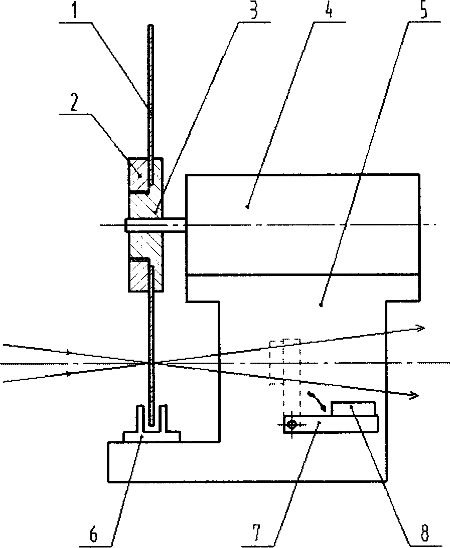
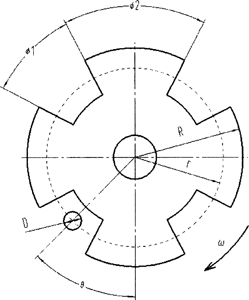
[0013] Such as figure 1 As shown, an opaque thin disc 1 with several axisymmetric openings is directly fixed on the shaft head of the high-speed motor 4 through the reverse threaded set nut 2 and the bushing 3, and the high-speed motor 4 and the photoelectric switch 6 are fixed On the base 5, a high-response speed photodiode 8 is installed at the rear position where the signal beam passes through the turntable 1, and the photodiode 8 is installed on a cantilever 7 that can be freely put into the optical path or taken away. The opening on the turntable 1 is not only the light-through hole for the incident signal, but also the positioning hole for the photoelectric switch 6. When the non-transparent part of the turntable 1 passes through the photoelectric switch, the photoelectric switch 6 gives a low-level signal; The opening passes through the photoelectric switch 6, and the photoelectric switch 6 gives a high-level signal. When the turntable 1 rotates continuously, the photoe...


PUM


Abstract

This invention discloses a rotary disc mechanic shutter of high repeating frequency and accuracy for switch controlling of light signals. A thin light-tight rotary disc with some holes is fixed on the generator spindle nose through clamp nut and axle sleeve. A photoelectric switch that fixed on the socket records the rotation information. A moveable photodiode probe is installed in the back of the disc where signal beams come through. The said mechanical shutter can be applied to some fields such as laser radar, laser ranging, laser space communication and laser satellite in self-adaptive optics.

Description

technical field [0001] The invention relates to a high-repetition-frequency and high-precision turntable mechanical shutter device, which is used for high-repetition-frequency and high-precision switch control of optical signals. Background technique [0002] In the application fields of laser radar, laser ranging, space laser communication, laser artificial guide star in adaptive optics technology, etc., it is necessary to detect targets at a certain distance. Its working system is to launch a laser pulse first, and then use the photodetector to receive the optical signal returned from the target after a certain time delay, and obtain effective information from the returned optical signal. In some applications, the repetition rate of pulsed laser emission and photoelectric reception is very high. For example, in the laser guide star in the adaptive optics technology, the repetition rate can reach hundreds of kilohertz. The time delay is proportional to the target distance...

Claims


Application Information

Patent Timeline
IPC IPC(8): G01D5/36G03B9/10
Inventor 李新阳王春鸿鲜浩李梅李明全任绍恒周璐春王晓云
Owner INST OF OPTICS & ELECTRONICS - CHINESE ACAD OF SCI
Learn More