
Hybrid dehumidifying air-conditioner

A hybrid and air-conditioning technology, applied in air-conditioning systems, heating methods, air treatment details, etc., can solve problems such as increased energy consumption, system performance degradation, overcooling, etc., to achieve reduced structural size, good heat transfer effect, and The effect of high quality and efficiency

Inactive Publication Date: 2005-01-26
SHANGHAI JIAO TONG UNIV
View PDF0 Cites 25 Cited by
  • Summary
  • Abstract
  • Description
  • Claims
  • Application Information

AI Technical Summary

Problems solved by technology

The traditional vapor compression air conditioner has the advantages of high heat transfer efficiency, compact structure, mature technology and convenient use; the disadvantage is that it consumes a lot of power, and it needs to be supercooled when dealing with latent heat load, which greatly increases energy consumption. Another disadvantage is that traditional refrigeration works High-quality freon will destroy the atmospheric ozone layer, and the use of new alternative working fluids will cause performance degradation of existing systems
The device is composed of a liquid dehumidifier, a regeneration device, an evaporator cooling device, and a compression refrigeration device. However, the use of a liquid desiccant for dehumidification is also insufficient. The main problem is the corrosion of the pipeline and the metal shell, and it also involves the regeneration of the liquid desiccant. The dehumidification system is bulky

Method used


Image

  • Hybrid dehumidifying air-conditioner

Examples


Embodiment Construction

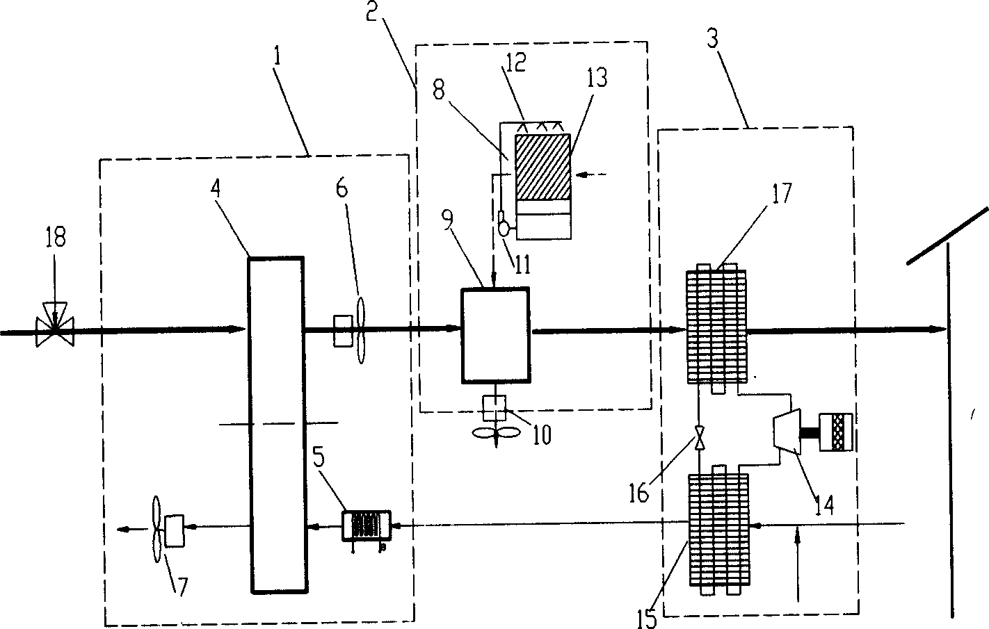
[0012] Such as figure 1 As shown, the present invention includes: a desiccant dehumidification subsystem 1, an indirect evaporative cooling device 2, and a vapor compression refrigeration subsystem 3. The three subsystems are connected through an air duct, and one end of the indirect evaporative cooling device 2 is connected to the desiccant dehumidification subsystem 1. , and the other end is connected to the vapor compression refrigeration subsystem 2.

[0013] Desiccant dehumidification subsystem 1 includes: rotary dehumidifier 4, regenerative heater 5, processing fan 6, regenerative fan 7, and rotary dehumidifier 4 are divided into two working areas: a dehumidification area and a regeneration area by a thermal insulation board , the outlet of the dehumidification area is connected to the processing fan 6 through the air duct, the inlet of the regeneration area is connected to the regeneration heater 5 through the air duct, and the outlet of the regeneration area is connect...


PUM


Abstract

The invention relates to a mixing humidity-removal air conditioner. It belongs to refrigeration and air conditioner technology field. The air conditioner includes desiccant humidity-removal subsystem, indirect evaporation refrigeration device and steam condensation refrigeration subsystem. Reel of desiccant humidity-removal subsystem is separated humidity-removal zone and regeneration zone by insulation heat preservation board. Exit of humidity-removal connects with fan through air conduit. Entry of regeneration connects with regeneration heater through air conduit. Exit of regeneration connects with regeneration wind fan. Two ends of sensible heat exchanger respectively connect with fan and direct evaporation condensation device. Two ends of air condition compressor of evaporation condensation subsystem respectively connect with evaporator and condensator. The other end of condensator connects with throttle device. The other end of throttle device connects with evaporator to form a loop. Adopting the invention, deep dry and evaporation condensation are reduced; evaporator's size is reduced; energy consumption and noise are reduced and heat pollution is lightened for fully using waste heat produced by system.

Description

technical field [0001] The invention relates to equipment and a new air treatment method used in the field of refrigeration and air-conditioning engineering, in particular to a hybrid desiccant air conditioner combining desiccant dehumidification and vapor compression refrigeration. Background technique [0002] The basic working principle of the desiccant air-conditioning system is desiccant dehumidification and evaporative cooling, which can realize the separate treatment of latent heat and sensible heat loads. It is very economical and practical to use as an air-conditioning system for commercial buildings in dry-heat and hot-humid climate areas. The traditional vapor compression air conditioner has the advantages of high heat transfer efficiency, compact structure, mature technology and convenient use; the disadvantage is that it consumes a lot of power, and it needs to be supercooled when dealing with latent heat load, which greatly increases energy consumption. Another ...

Claims


Application Information

Patent Timeline
IPC IPC(8): F24F3/06F24F3/14F24F3/147
CPCF24F2203/1024F24F2203/1016F24F2203/1056F24F3/1423F24F2203/1084F24F2203/1068F24F2203/1032
Inventor 代彦军贾春霞王如竹吴静怡
Owner SHANGHAI JIAO TONG UNIV
Learn More