
Vehicle-carrying automatically passing neutral section system of electric locomotive

A technology for automatic phase separation and electric locomotives, applied in electric vehicles, electric vehicle charging technology, collectors, etc., can solve problems such as current impact, train impulse, locomotive speed loss, etc., and achieve high reliability, equipment reduction, and automation performance high effect

Inactive Publication Date: 2005-01-26
深圳市三英特高科技有限公司
View PDF1 Cites 14 Cited by
  • Summary
  • Abstract
  • Description
  • Claims
  • Application Information

AI Technical Summary

Problems solved by technology

The traditional phase separation method for electric locomotives is that the locomotive driver manually switches the main circuit breaker of the locomotive power supply according to the breakout signs set on the line. The main problem of this manual operation through the phase separation area is: On the line, the locomotive has to pass through more than ten phase-separation zones per hour. When passing through the phase-separation zones frequently, it is difficult to grasp the best split-main break time by manual operation, and it is also impossible to control the best current drop and current rise rates, resulting in More locomotive speed loss and greater locomotive impulse
The disadvantages of these two schemes are: the vacuum load switch breaks with load, there is a large current impact, and the equipment investment is huge
The disadvantage of this solution is that the locomotive is powered off for a period of time. If the power off time is too long, it will cause a large loss of locomotive speed. If the current is reduced and the current is raised too fast, current shock and train impulse will occur.
Although this invention utilizes the TAX box kilometer mark locomotive to be able to simulate the driver's operation automatically, and has improved the automation process, there are the following disadvantages: 1. The generation of the kilometer mark distance is obtained by manual correction and vehicle speed accumulation, and manual correction exists The problem of misoperation; and the speed of the vehicle is generated by counting the pulses based on the input wheel diameter
The input of the initial value of the wheel diameter is also manual, and sometimes there will be a large error; 2. In the rainy and snowy season, the wheels will inevitably slip. Even if the wheel diameter value can be input manually, it will inevitably cause Large error; 3. The kilometer mark of the TAX box passes through multiple links such as the pulse sensor, the operation meter, and the TAX box. A failure in any link will cause a fault in the signal of the kilometer mark. There is no supervision mechanism for the fault of the signal of the kilometer mark It may not be discovered before the excessive phase; 4. There is no control mechanism for reducing current and increasing current rate, which will inevitably cause the impulse of the train, especially for express trains. This phenomenon is not allowed; 5. The locomotive can only Running on the line, if the line is changed, professional and technical personnel must re-collect points, make a table, and send it to the computer. The operation is very troublesome, which is not conducive to large-scale promotion and locomotive mobilization.
[0005] In addition, our country also has an automatic over-phase separation system based on buried magnets. The positioning and identification of this scheme relies solely on the installation of magnets on the sleepers. , the sensor must have a high sensitivity, and if the sensitivity is too high, it will misidentify the general magnetic bodies scattered on the roadbed or sleepers at high speed, which will reduce the reliability of excessive phase positioning; the magnets buried in the sleepers are due to Strong magnetism, it is very easy to absorb the magnetic or ferrous substances scattered nearby, changing the magnetic field distribution, greatly reducing the reliability of the magnetic induction current sensor identification; due to other reasons such as the loss or failure of the ground induction magnet, missed detection is prone to occur Excessive charging is equivalent to driving accidents; in order to prevent the magnet from being lost, the magnet is cast in the sleeper, which involves many departments and is difficult to construct and maintain

Method used


Image

  • Vehicle-carrying automatically passing neutral section system of electric locomotive
  • Vehicle-carrying automatically passing neutral section system of electric locomotive
  • Vehicle-carrying automatically passing neutral section system of electric locomotive

Examples


Embodiment Construction

[0034] Below in conjunction with accompanying drawing, the present invention will be further described:

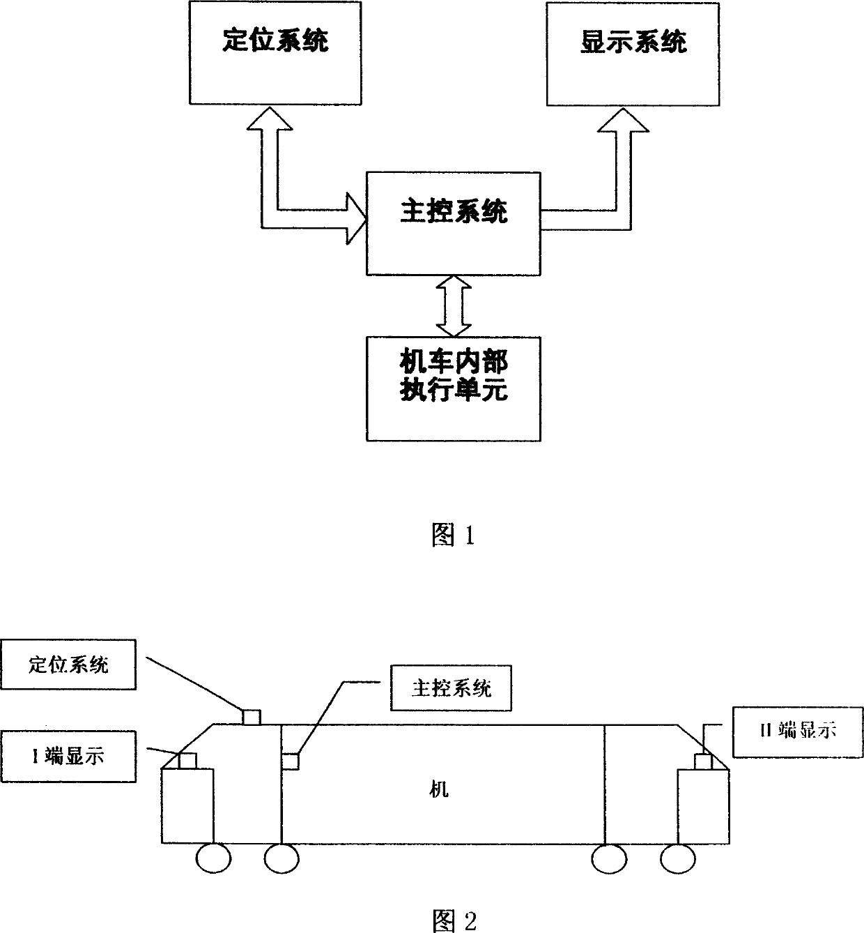
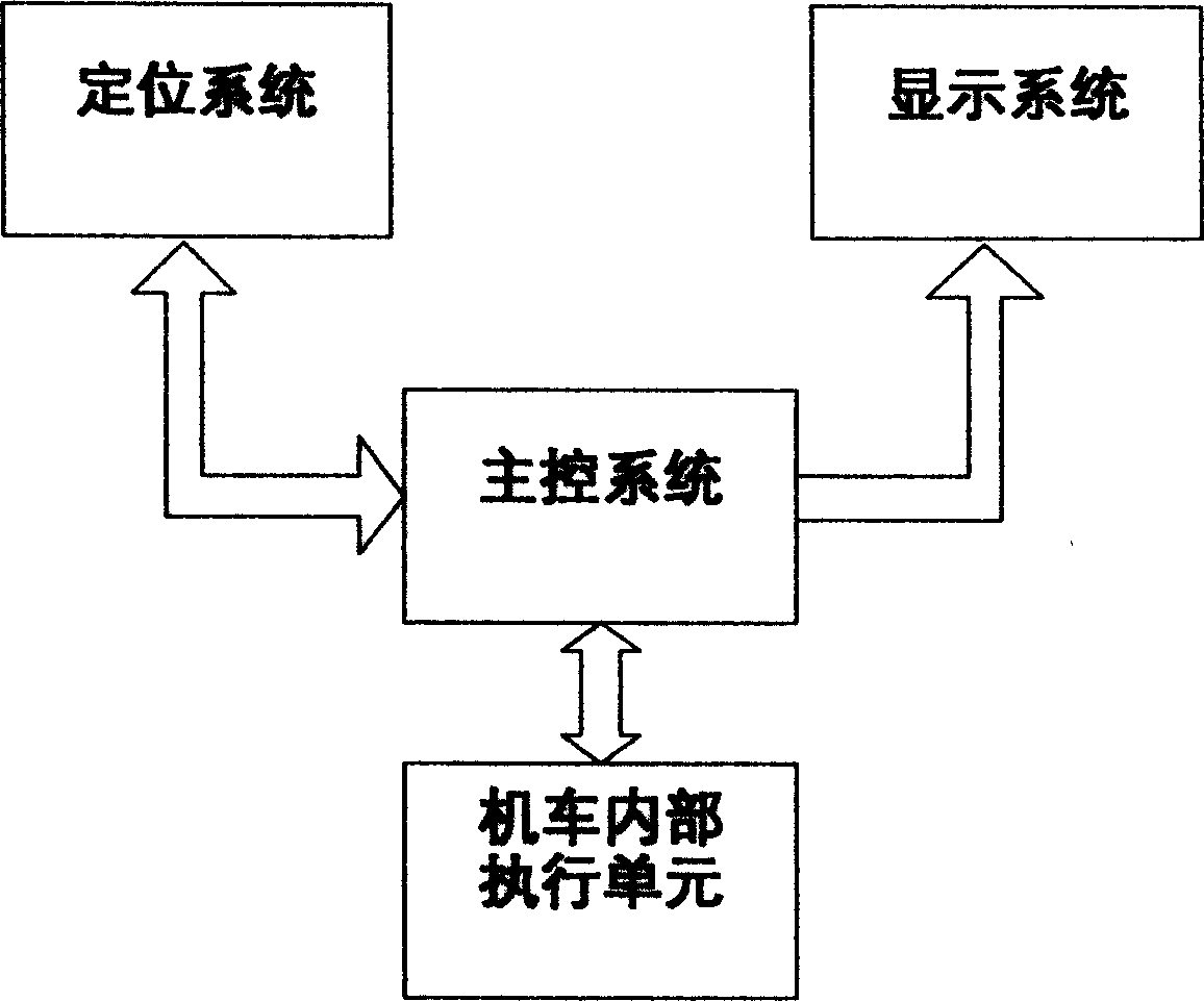
[0035] The vehicle-mounted automatic phase separation system structure of the present invention is shown in Figure 1. The present invention includes a positioning system, a main control system, a display system, and also includes a main control program and a positioning system program. The positioning system and the display system are respectively connected to the main control system through cables, and the positioning system is composed of a radio frequency identification system (RFID) and a GPS satellite positioning system. Positioning system programs include radio frequency identification system (RFID) programs and GPS satellite positioning system programs.

[0036] In Fig. 1 and Fig. 4, the positioning system includes a radio frequency identification system (RFID), which is composed of an identifier and a radio frequency card. The identifier is connected to the top of...


PUM


Abstract

The invention discloses car carrying over split phase system, providing a system for car and vehicle passes the split phase stably and safely which not only can judge the position at front of the split phase point, but also can control the velocity of decreased current and upgraded current. The invention includes localizing system, primary control system, displaying system, primary controller procedure and localizing system procedure. The localizing system is made up of radio frequency identification system (RFID) and GPS localizing system. The localizing system procedure includes radio frequency identification system procedure and GPS localizing system procedure. The localizing system and the displaying system are connected to the primary control system through cables. The radio frequency identification system is made up of identifier and radio frequency card. The primary system includes a power, primary controller and external signal circuit, the external signal circuit is connected to the primary controller. The displaying system includes digital code tube, LED display, primary microchip and peripheral hardware circuit.

Description

technical field [0001] The invention relates to a control device for over-phase separation of an electric locomotive, in particular to a control device for an automatic over-phase separation system mounted on an electric locomotive. Background technique [0002] In the electrified traction section, the traction power supply network adopts the single-phase power frequency AC power supply mode. In order to make the three-phase balance of the power system and improve the utilization rate of the power grid, the power supply catenary of the electrified railway adopts segmental commutation power supply, and there is a section of insulator at the commutation point to electrically separate the two-phase catenary, which is called the phase separation area. . In order to avoid damage to the power supply equipment by dragging arc, the electric locomotive must power off and coast when passing through the phase separation area. The traditional phase separation method for electric locom...

Claims


Application Information

Patent Timeline
IPC IPC(8): B60L5/36
CPCY02T90/16
Inventor 王小可
Owner 深圳市三英特高科技有限公司
Learn More