Micromachine vibration filter
A micro-mechanical and filter technology, applied in the filter field, can solve the problems of weak vibration signal, smaller beam vibration amplitude, and superposition of noise, and achieve the effect of suppressing the decline of output signal strength and preventing weakening
- Summary
- Abstract
- Description
- Claims
- Application Information
AI Technical Summary
Problems solved by technology
Method used
Image

Examples
Embodiment 1
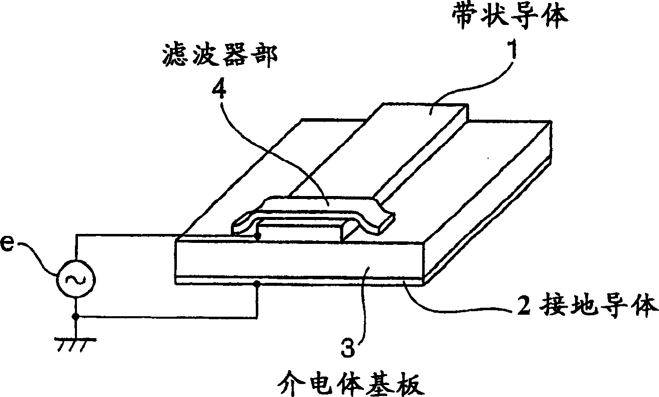
[0055] image 3 It is a schematic diagram of the micromechanical vibration filter of Embodiment 1 of the present invention. The waveguide is a microstrip line type, and the strip conductor 1 and the ground conductor 2 are provided with a dielectric substrate 3 in between, and a filter part 4 is formed on a part of the strip conductor 1, and the signal source e is connected to the strip conductor 1 and the ground conductor. between 2.
[0056] Figure 4 It is a side sectional view of the filter unit 4 . Micro-cylindrical single-support micro-cylindrical beams 5 composed of a plurality of conductors stand in an array on the strip conductor 1 . In addition, if Figure 5 Partial enlarged side section view of and Figure 6 As shown in the partially enlarged plan view of , there is a gap g around the front end of the micro-cylindrical beam 5 1 , g 2 A detection electrode 6 is provided. In the present embodiment 1, the detection electrode 6 is a flat plate surrounded by the m...
Embodiment 2
[0069] Figure 8 Related to Embodiment 2 of the present invention, its overall structure is the same as image 3 The shown embodiment 1 is the same, but in this embodiment 2, a pair of micro cylinders 5a, 5b facing the micro cylinder beam 5 are arranged side by side in an array, and a micro cylinder beam 5a forms a capacitor with the common detection electrode 6a respectively , the front end of the other micro-cylindrical beam 5b is respectively fixed on the common detection electrode 6b through the fixing material 9 . Figure 9 In its plan view, the micro-cylindrical beams 5a, 5b are respectively arranged opposite to the detection electrodes 6a, 6b with a gap of g, and the detection electrodes 6a, 6b are arranged opposite to each other at an interval A. The detection electrode 6 a is connected to the first comparator 7 b of the detection circuit 7 , and the detection electrode 6 b is connected to the second comparator 7 c of the detection circuit 7 .
[0070] By the signal ...
Embodiment 3
[0073] Figure 10 and Figure 11 It is a plan view and a side view of the micromechanical vibration filter according to the third embodiment of the present invention. Part of the strip conductor 1 of the microstrip type is replaced by a plurality of coil springs 10 serving as a micromechanical vibrator connected in parallel in an array. However, if Figure 10 As shown, the two ends of the coil spring 10 are installed at an angle θ to the direction of the transmission path. Since the coil spring 10 is slightly bent at its center to form an opening 11, if a current flows through the coil spring 10, the internal magnetic flux becomes The state of leaking from the opening 11. However, since a force that maximizes the magnetic energy inside the coil spring 10 acts on the coil spring, the coil spring 10 closes the opening 11 to be in a linear state. Due to this force, the coil spring 10 vibrates at a natural resonant frequency. This mechanical vibration is detected as a change ...
PUM
 Abstract
Description
Claims
Application Information
 - R&D
- Intellectual Property
- Life Sciences
- Materials
- Tech Scout
- Unparalleled Data Quality
- Higher Quality Content
- 60% Fewer Hallucinations
Browse by: Latest US Patents, China's latest patents, Technical Efficacy Thesaurus, Application Domain, Technology Topic, Popular Technical Reports.
© 2025 PatSnap. All rights reserved.Legal|Privacy policy|Modern Slavery Act Transparency Statement|Sitemap|About US| Contact US: help@patsnap.com