
Fryer

A frying pan and oil tank technology, which is applied to utensils for frying things in oil, utensils for boiling water, cooking utensils, etc. question

Inactive Publication Date: 2004-03-24
超级厨具株式会社
View PDF1 Cites 8 Cited by
  • Summary
  • Abstract
  • Description
  • Claims
  • Application Information

AI Technical Summary

Problems solved by technology

[0007] (4) The time of frying increases
[0008] (5) The antibacterial properties of fried foods need to be improved
[0009] (6) The anti-corrosion of fried food needs to be improved
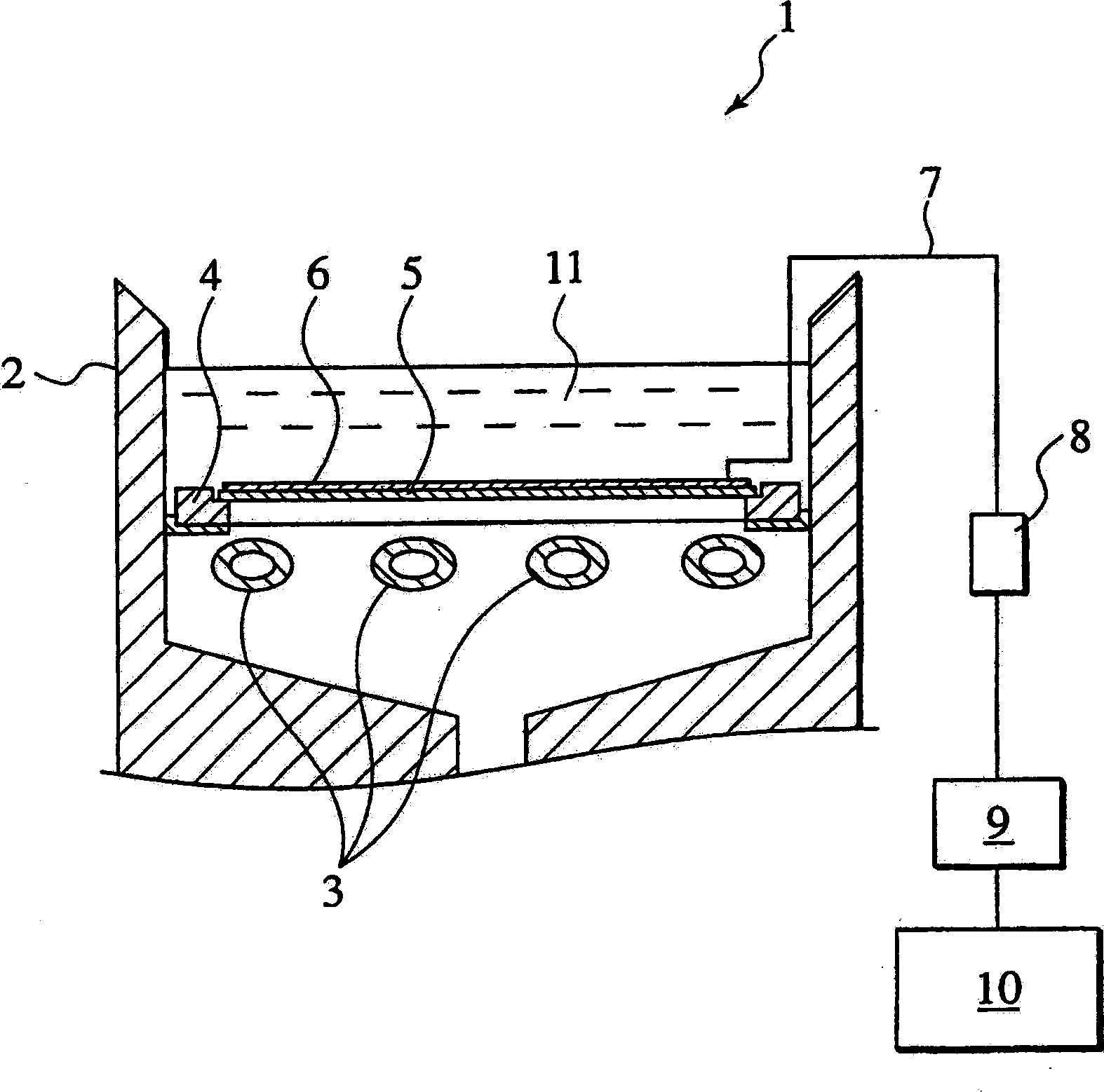
[0012] However, in the above-mentioned fryer 1, the electric field generated by the high voltage and weak current is only limited to the periphery of the current-carrying plate 5, and the oil outside the electric field is difficult to suppress its oxidation because it is not exposed to the electric field of the high voltage and weak current.
[0013] In addition, when frying food is placed in a position other than the periphery of the current-carrying plate 5, the effect of the electric field cannot reach, and the above-mentioned problem is difficult to be solved.
[0014] In addition, by making the oil groove 2 out of a conductor and facing it with the current-carrying plate 5, the oil groove 2 itself is used as a counter electrode, although it can be considered that the area where the electric field acts is widened, a weak current flows through the oil groove 2 itself. Not ideal from the perspective of user safety
[0015] Have again, although the top of the energization plate 5 is covered by the insulating plate 6, because there are exposed areas below and in the holes of the insulating plate 6, it is possible to make the moisture dissolved in the fried food and the oxidation caused by the high-temperature oil The polymer adheres to the current-carrying plate 5, and weak electric leakage and transformer damage occur in a short time

Method used


Image

  • Fryer
  • Fryer
  • Fryer

Examples


no. 1 example

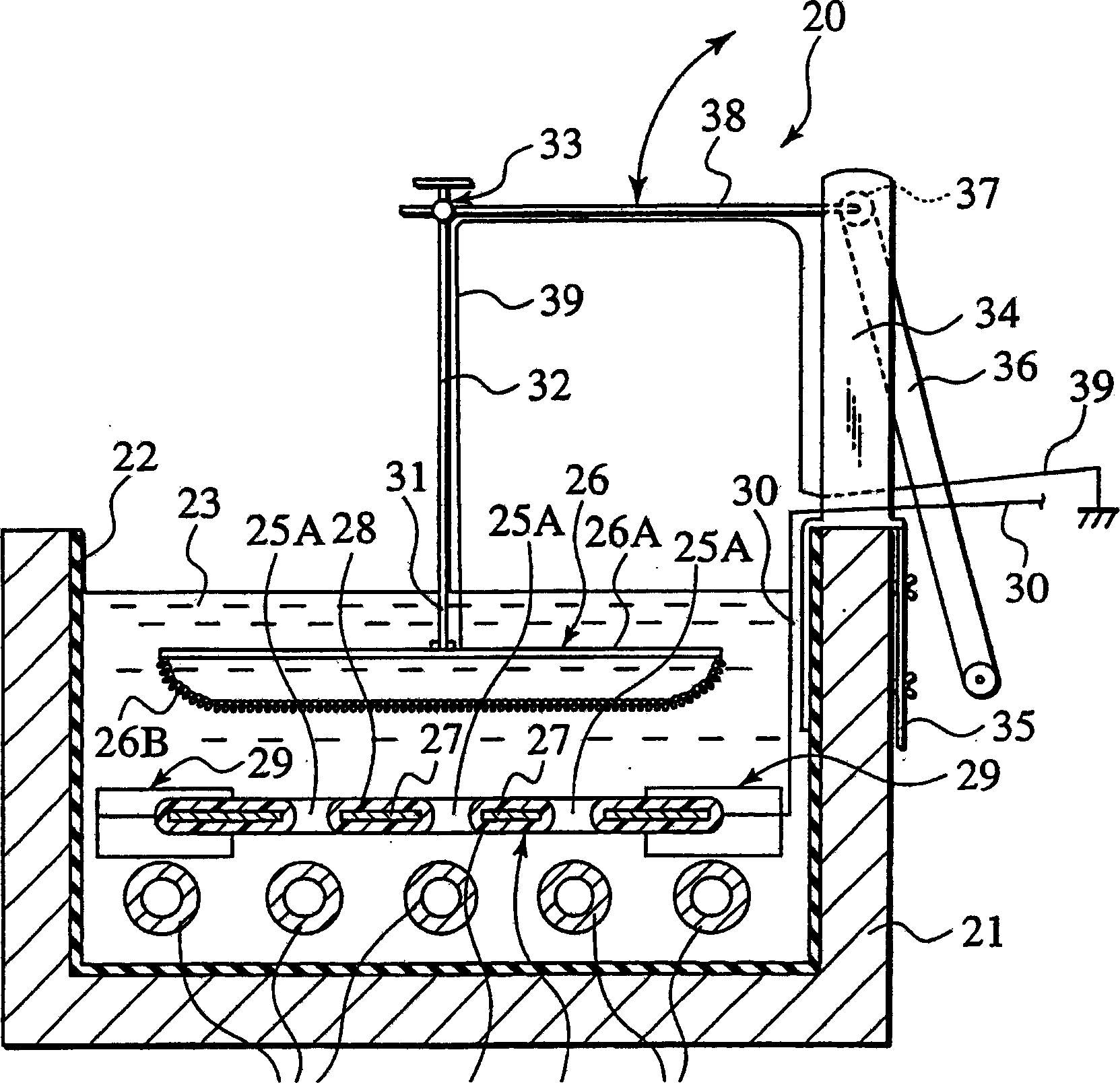
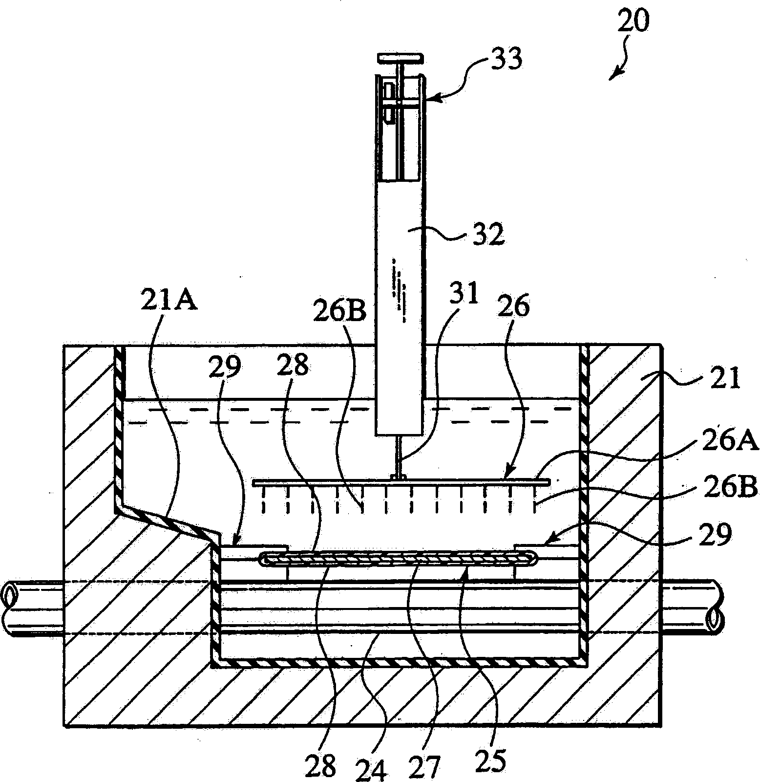
[0046] Figure 2 ~ Figure 6 Shown is a first embodiment of a fryer according to the invention. The first embodiment is an example in which the present invention is applied to a gap type fryer. figure 2 It is a sectional view of fryer 20 seen from the side ( Image 6 II-II sectional view); image 3 It is a cross-sectional view seen from the front ( Image 6 III-III sectional view); Figure 4 is a perspective view of the ground plate 26; Figure 5 It is a plan view showing the state where the electrode plate 25 is arranged in the oil tank 21; Image 6 It is a plan view of fryer 20.

[0047] The deep fryer 20 of this first embodiment, as figure 2 and image 3 As shown, the electric field shielding layer 22 formed substantially by the oil tank 21 , covering the entire inner surface of the oil tank 21 , several heating tubes 24 for heating the frying oil 23 contained in the oil tank 21 , and the heating tubes 24 are arranged. The electrode device 25 directly above is con...

no. 2 example

[0060] Figure 7 ~ Figure 10 Shown is a second embodiment of the deep fryer of the present invention. The fryer of the second embodiment is also gap type. Figure 7 It is a sectional view of fryer 40 seen from the side ( Figure 10 XII-XII sectional view), Figure 8 is a cross-sectional view seen from the front ( Figure 10 XIII-XIII sectional view), Figure 9 is a plan view of the state where the ground plate is arranged, Figure 10 It is a plan view showing the state where the electrode plate is arranged in the oil tank.

[0061] The deep fryer 40 of this second embodiment, as Figure 7 and Figure 10 As shown, the electric field shielding layer 42 formed substantially by the oil tank 41, covering the entire inside of the oil tank 41, several heating tubes 44 for heating the cooking oil 43 contained in the oil tank 41, are arranged directly above the heating tube 44. The ground plate 45 is formed by an electrode device 46 that is disposed opposite to the ground plate...

no. 3 example

[0073] Figure 11 and Figure 12 Shown is the third embodiment of the deep fryer of the present invention. In the fryer 60 of the third embodiment, the electric field shielding layer 62 is formed on the entire inner surface of the oil tank 61 . In addition, the heating pipe 63 disposed in the oil groove 61 is arranged to be introduced into the oil groove 61 from one side of the side wall, and is bent into a substantially Z shape at the bottom of the oil groove 61 to lead to the outside from the other side of the side wall. form. Therefore, in the third embodiment, it is not necessary for the heating pipe 63 to pass through the oil groove 61 .

[0074] Also, in the third embodiment, the electrode device 64 is provided to be freely raised and lowered by being driven to move up and down together with the raising and lowering frame 65 . In addition, in the fryer 60 of the third embodiment, a ground plate not shown may be arranged below the electrode device 64 or may be arrange...


PUM


Abstract

An electrode unit 25 applied with a high voltage and a grounded earth plate 26 are disposed in an oil bath 21 in a mutually opposed relationship, and an electric field shielding layer 22 made of insulation material is disposed so as to surround a frying region between the electrode unit and the earth plate 26, with the electrode unit 25 being applied with the high voltage to create a high-voltage weak current in the frying region. For this reason, a safety of a user can be enhanced, permitting the high-voltage weak current to afford a preferable influence to food material.

Description

technical field [0001] The present invention relates to a deep fryer for frying food, more particularly, to a gap type deep fryer equipped with an electric field generating device in an oil tank. Background technique [0002] This kind of fryer heats the cooking oil in the oil tank by heating from the outside of the oil tank, and is generally used to make fried shrimp and fried food. When using such a general fryer, there is a problem that the oil in the oil tank is easily deteriorated and discolored due to oxidation due to heat. In addition, there is also a problem that fried foods are prone to spoilage due to oxidation of the oil. As specific problems when frying food with such a deep fryer, there are the following points: [0003] (1) Fried food absorbs a lot of oil and cannot be fried thoroughly. [0004] (2) After frying, the water and nutrients of the fried food are dissolved in the oil and lose their taste. [0005] Also, the fries will be smaller reducing the por...

Claims


Application Information

Patent Timeline
Patent Type & Authority Applications(China)
IPC IPC(8): A47J27/21A47J37/12
CPCA47J37/1257A47J27/21025
Inventor 阿部武彦石関荣一
Owner 超级厨具株式会社
Learn More