
Electron tube

A technology of electron tubes and electrons, applied in the field of electron tubes, can solve problems such as the reduction of electron emission efficiency

Inactive Publication Date: 2004-03-17
HAMAMATSU PHOTONICS KK
View PDF1 Cites 1 Cited by
  • Summary
  • Abstract
  • Description
  • Claims
  • Application Information

AI Technical Summary

Problems solved by technology

Also, since the electron emission efficiency may be greatly reduced due to its state change, this change creates a series of problems in terms of the performance of field emitters

Method used


Image

  • Electron tube
  • Electron tube
  • Electron tube

Examples


Embodiment Construction

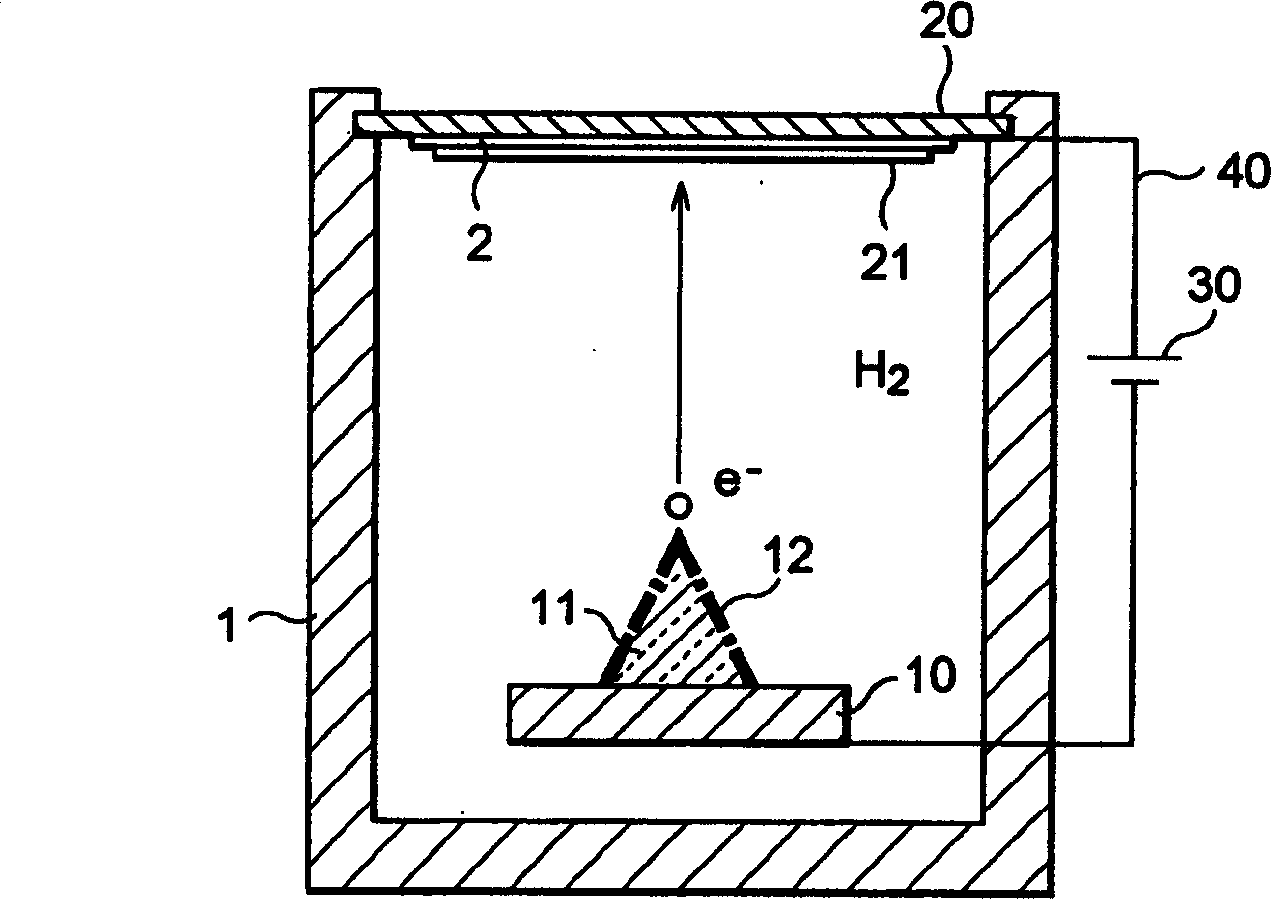
[0028] Below, refer to Figure 2 to Figure 13 , A detailed description of the preferred embodiment of the present invention. In the figure, components that are the same or equivalent to each other are given the same reference numbers.

[0029] figure 2 It is a side sectional view showing the structure of the electron tube according to the first embodiment of the present invention. In order to explain the basic operation, the electronic system and components are arranged corresponding to a single pixel.

[0030] Such as figure 2 As shown, the electron tube of the first embodiment of the present invention has a diode structure. In other words, in the sealed package 1, the field emitter 11 having the point-shaped end is provided on the conductive flat plate 10. The phosphor 21 (phosphor screen) formed in a film shape as an anode is provided on the light-transmitting conductive film 2 on the glass plate 20 and faces the end of the field emitter 11. The field emitter 11 is preferabl...


PUM


Abstract

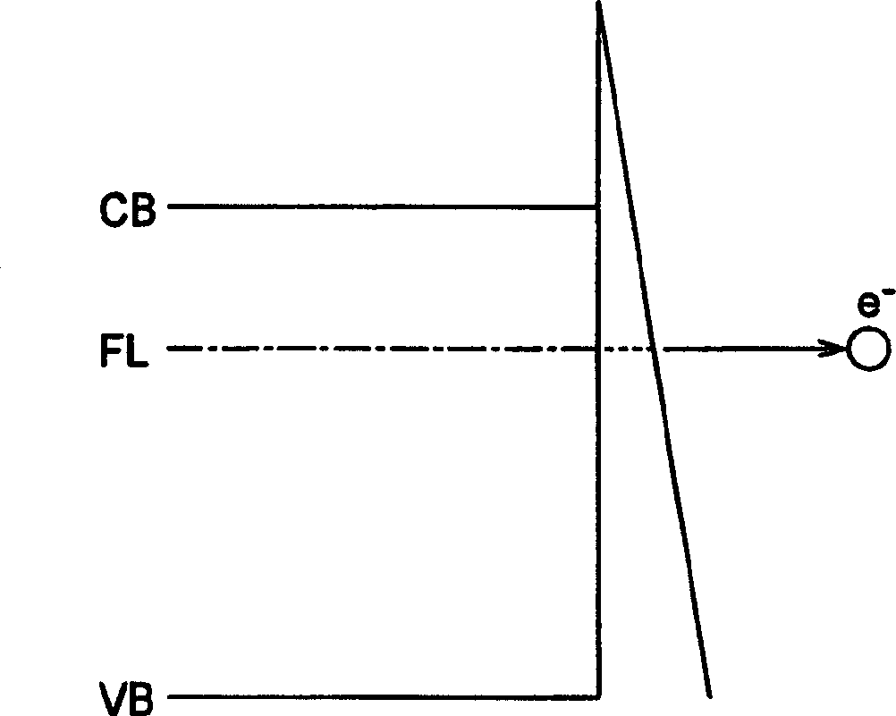
The present invention relates to an electron tube having a configuration which can maintain its operating stability for a long period of time. The electron tube comprises, at least, a field emitter which is made of diamond or a material mainly composed of diamond and has a surface terminated with hydrogen, and a sealed envelope for accommodating the diamond field emitter. Due to the hydrogen termination, the electron affinity of the diamond field emitter is set to a negative state. Also, hydrogen is enclosed within the sealed envelope. Due to this configuration, the hydrogen-terminated state of the diamond field emitter surface is stabilized, and the electron affinity of the diamond emitter is restrained from changing for a long period of time.

Description

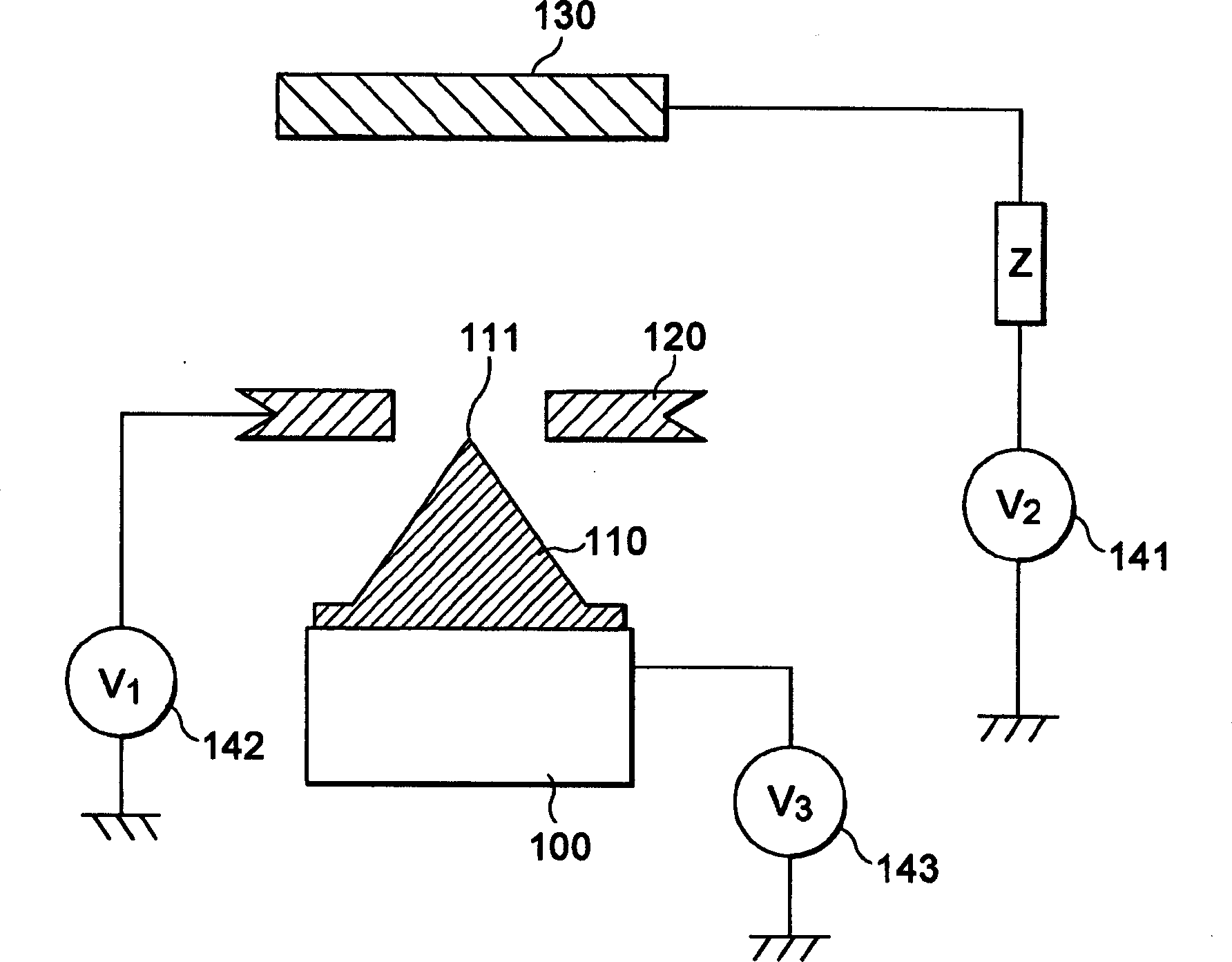
[0001] This application is based on the divisional application of the invention patent application No. 97120094.7 entitled "Electronic Tube" on October 13, 1997. Technical field [0002] The present invention relates to an electron tube, in particular to an electron tube with a field emitter. Background technique [0003] As the field emitter used for the electron beam source of the electron tube, it is well known that there are generally a hot cathode type and a field emission type. In recent years, the field emission type electron source has attracted more attention because of its high electron emission density. Generally, semiconductors such as silicon or high melting point metals such as molybdenum or tungsten are used as materials for such field emitters. Recently, for example, in EP-B1-0523494 and Japanese Patent Publication No. 7-29483, electron tubes with field emitters made of diamond or a material mainly composed of diamond have been disclosed. [0004] figure 1 It is ...

Claims


Application Information

Patent Timeline
IPC IPC(8): H01J31/12H01J1/304H01J7/02H01J29/04H01J29/94
CPCH01J2201/30457H01J29/94H01J2329/00H01J2201/30426H01J1/304
Inventor 新垣实广畑彻菅博文山田正美
Owner HAMAMATSU PHOTONICS KK
Learn More