
Clamping casting type combined branch cable and making method thereof

A branch cable, cable technology, applied in cable/conductor manufacturing, insulated cables, cables, etc., can solve the problems of cable detachment and small contact area, and achieve the effect of enhanced tensile force and increased contact area

Inactive Publication Date: 2003-08-06
杨恒新
View PDF0 Cites 4 Cited by
  • Summary
  • Abstract
  • Description
  • Claims
  • Application Information

AI Technical Summary

Problems solved by technology

The defect of this kind of cable is: the contact of two cylindrical cables is line contact, the contact area is too small, when the splint is slightly loose, the two cables will be separated

Method used


Image

  • Clamping casting type combined branch cable and making method thereof
  • Clamping casting type combined branch cable and making method thereof

Examples


Embodiment Construction

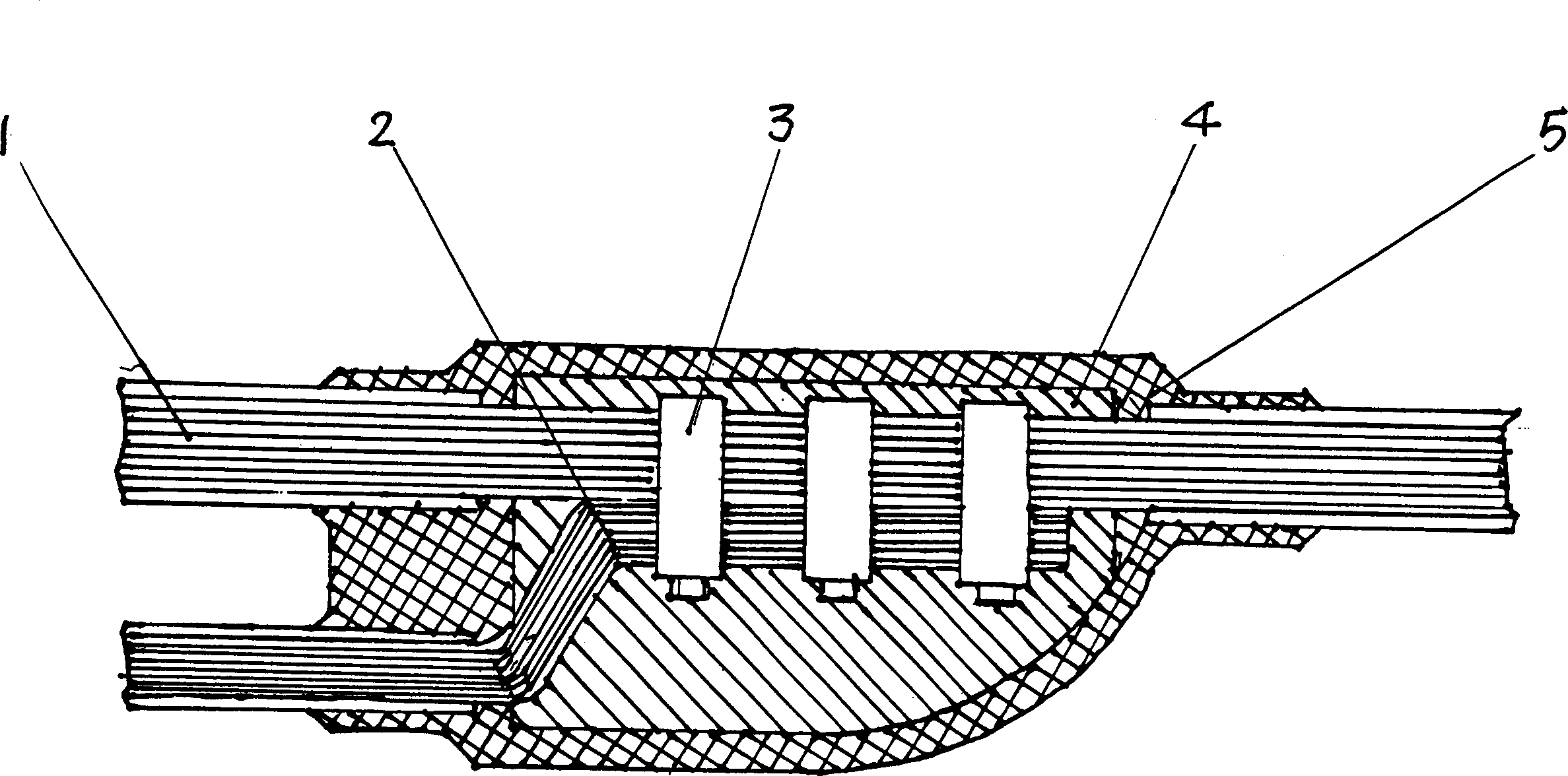
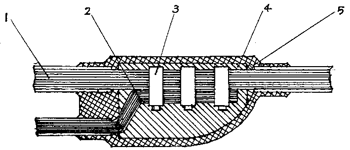
[0012] It includes a main cable 1 and a branch cable 2, the junction of the two is fixed by a splint 3, and there is a cast aluminum protective sheath 4 at the junction of the two, the cast aluminum sheath is cast as one with the two cables and the splint The outside of the protective cover is a rubber and plastic insulation cover 5.

[0013] The manufacture method of the present invention is:

[0014] (1) Strip the joints of the main cable and branch cables;

[0015] (2) Clamp and fix the main cable and branch cable at the joint with a splint;

[0016] (3) Cast aluminum at the joint;

[0017] (4) The outer skin at the joint is injection molded with insulating polyvinyl chloride at one time.


PUM


Abstract

This invention provides a clip-casting combined branch cable and its process method. The existing shortcoming is that contact of two cylindrical cables is linear with two small contact area and a slight loose of the clamp plate will cause separation of the two cables showing that the combined branch cable has small stretching resistance. This invented technology scheme is that it includes a main and a branch cable, their contact part is fixed by a clamp plate with a cast A1 protecting jacket becoming an entire unit, and a rubber plastic insulation jacket covers the cast A1 protecting jacket and joints of the main and branch are casted with A1.

Description

【Technical field】 [0001] The invention relates to a cable and its manufacturing method, in particular to a branch cable for high-rise building power transmission and its manufacturing method. 【Background technique】 [0002] Plug-in busbar is a traditional way to transmit power to high-rise buildings. Using this method to transmit electricity requires a large area, many connectors, and exposed connectors, which are prone to corrosion over time, resulting in ignition points and accidents. In order to solve this problem, people have invented a combined branch cable to replace the plug-in busbar. The combined branch cable is composed of the main cable and the branch cable after the junction is clamped with a splint. The defect of this cable is: the contact of two cylindrical cables is a line contact, and the contact area is too small, and when the splint is slightly loose, the two cables will break away. Therefore, the tensile force of this combined branch cable is small. 【...

Claims


Application Information

Patent Timeline
IPC IPC(8): H01B7/17H01B13/00
Inventor 杨恒新
Owner 杨恒新
Learn More