Air cooling apparatus and air cooling method
An air cooling and air technology, applied in office buildings and hospitals, can solve the problems of insufficient utilization and low thermal efficiency
- Summary
- Abstract
- Description
- Claims
- Application Information
AI Technical Summary
Problems solved by technology
Method used
Image


Examples
Embodiment 1
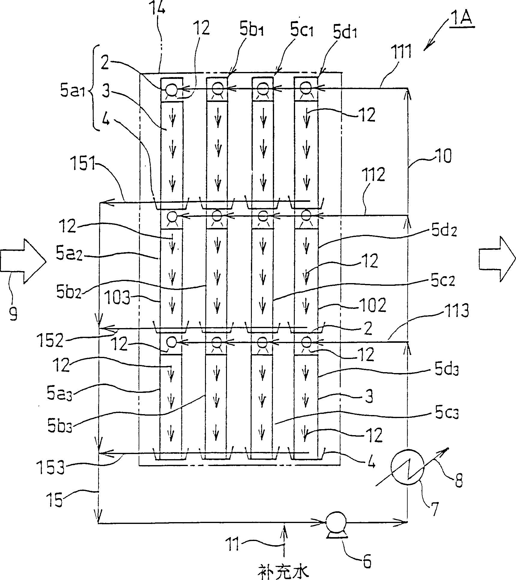
[0045] Glass non-woven fabric made of E-glass fiber and organic binder is dipped in a slurry containing alumina hydrate as a filler material and alumina gel as a binder, dried, and processed to form waves to obtain a waveform thing. The corrugated objects are laminated alternately so that the propagation direction of the wave intersects, and then heat-treated at a temperature of 500°C to form a total amount of 80% by weight of alumina and alumina gel hardened product and 20% by weight of E-glass fiber. , a diagonal honeycomb body with a porosity of 65%, a tooth height of 4.8mm and a pitch of 10mm. The oblique honeycomb body is 1000mm wide relative to the ventilation direction of the air, the height is 400mm, and the depth is 200mm. figure 1 The symbol Y) in is 60 degrees, the inclination angle relative to the air inflow and outflow direction (horizontal direction) when viewed from the front and back sides of the units arranged obliquely ( figure 1 The symbol X) in is 30 degr...
reference example 1
[0048] The cooling unit uses an oblique honeycomb body with a width of 1000mm, a height of 1200mm, and a thickness of 200mm. After including the water supply pan and drain pan, the cooling unit is configured with a width of 1000mm, a height of 1300mm, and a depth of 200mm. Arranged in 1 layer and 1 row. A total of 1 unit), except for using a case with the same shape and a size that can be installed in the cooling unit, measure the temperature and humidity of the outlet air and the pressure loss of the air cooling device in the same manner as in Example 1. . The conditions and measurement results of the cooling unit and the like are shown in Tables 1 to 3. In addition, in this example, a considerable amount of cooling water is scattered with the wind to the leeward side of the honeycomb body during operation. This is considered to be due to the same L / G as Example 1, L / G 400-200 It is larger than Example 1, and it is caused by too much cooling water in the depth direction of ...
Embodiment 3
[0054] Except that the cooling unit made in Example 1 is 1000mm in width, 1500mm in height, and 600mm in depth by 3 layers up and down, and 3 rows in the front and rear openings (the cooling unit is arranged in 3 layers and 3 rows, and the total There are 9 units.) Except, constitute the same device as embodiment 1, measurement conditions are as shown in table 3 and table 4, measure the temperature of outlet air, humidity and the pressure loss of air cooling device. In addition, since this embodiment assumes the cooling of the external air inlet for the clean room of the semiconductor factory, the content of impurity ions in the air at the inlet and the amount of impurity ions in the cooled air were also measured. removal rate. The ion concentration of impurity is obtained by analyzing the collected liquid with ion chromatogram after the impingement dust detector added with ultrapure water absorbs the air at the inlet of the collected air and the cooled air respectively. The ...
PUM
 Abstract
Description
Claims
Application Information
 - R&D
- Intellectual Property
- Life Sciences
- Materials
- Tech Scout
- Unparalleled Data Quality
- Higher Quality Content
- 60% Fewer Hallucinations
Browse by: Latest US Patents, China's latest patents, Technical Efficacy Thesaurus, Application Domain, Technology Topic, Popular Technical Reports.
© 2025 PatSnap. All rights reserved.Legal|Privacy policy|Modern Slavery Act Transparency Statement|Sitemap|About US| Contact US: help@patsnap.com