Dynamic power control in integrated circuit

A power control, integrated circuit technology, applied in data processing power supply, electrical digital data processing, instruments, etc., can solve problems such as unsatisfactory, energy consumption, unpredictable delay time, etc., to achieve simplified structure and testing, power saving , the effect of saving power

Inactive Publication Date: 2003-07-02
NOKIA TECHNOLOGLES OY
View PDF1 Cites 18 Cited by
  • Summary
  • Abstract
  • Description
  • Claims
  • Application Information

AI Technical Summary

Problems solved by technology

[0009] The prior art dynamic power reduction solutions described above have proven to be unsatisfactory, especially in solutions requiring a strong emphasis on power savings while accurately predicting system response times
When using state-of-the-art solutions, especially in more complex systems consisting of several hardware units, it is very difficult to "provoke" the delay time of the system's operation from power-down mode to standby mode under varying conditions Anticipated, where the system must be pre-energized slightly on the safe side prior to movement when the system should be ready for latest operation
This way, when the system is ready for operation but not yet performing any real function, it consumes power unnecessarily

Method used


Image

  • Dynamic power control in integrated circuit
  • Dynamic power control in integrated circuit
  • Dynamic power control in integrated circuit

Examples


Embodiment Construction

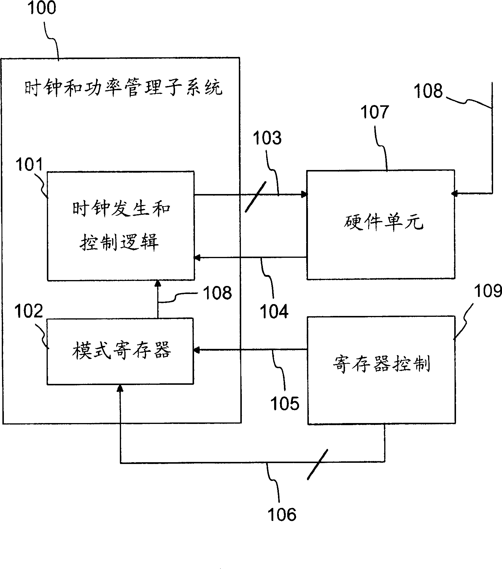
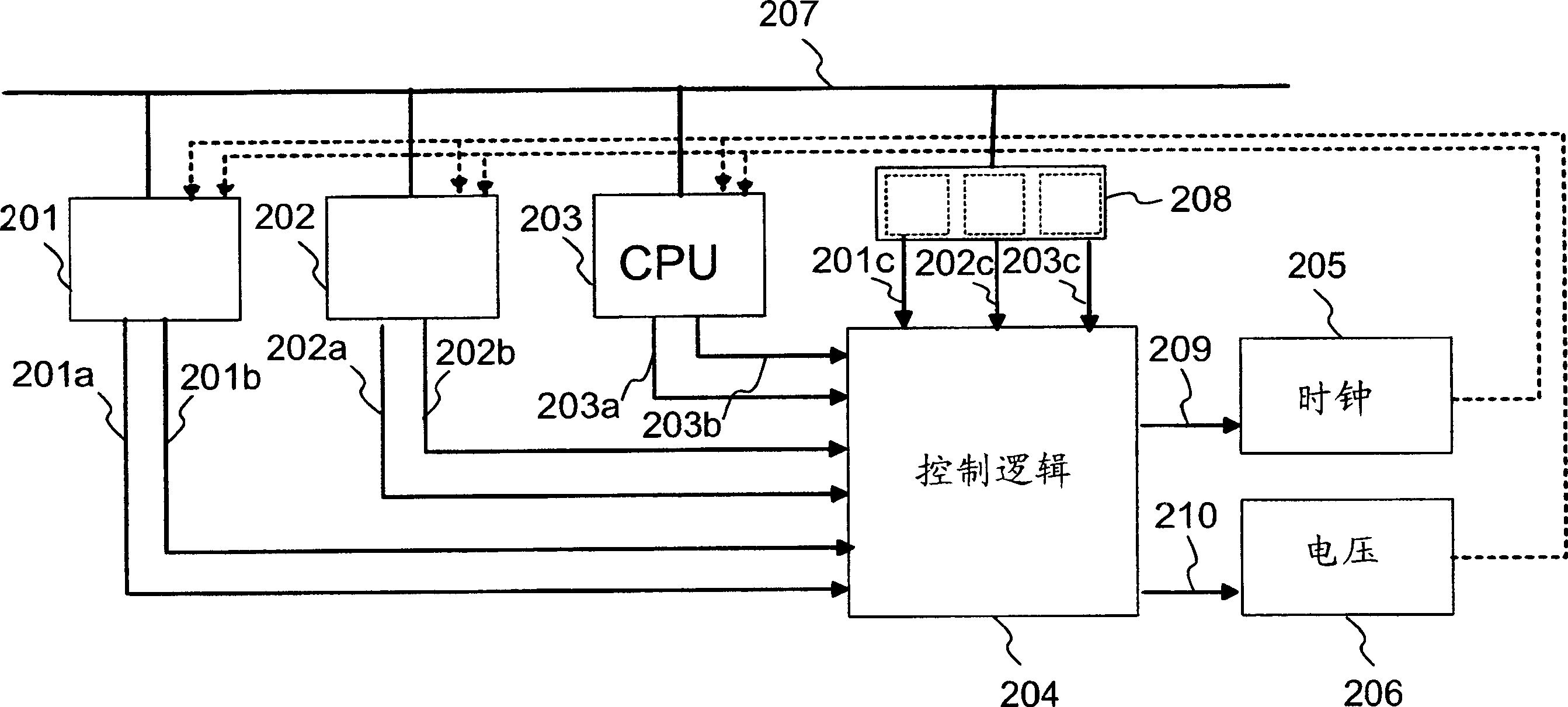
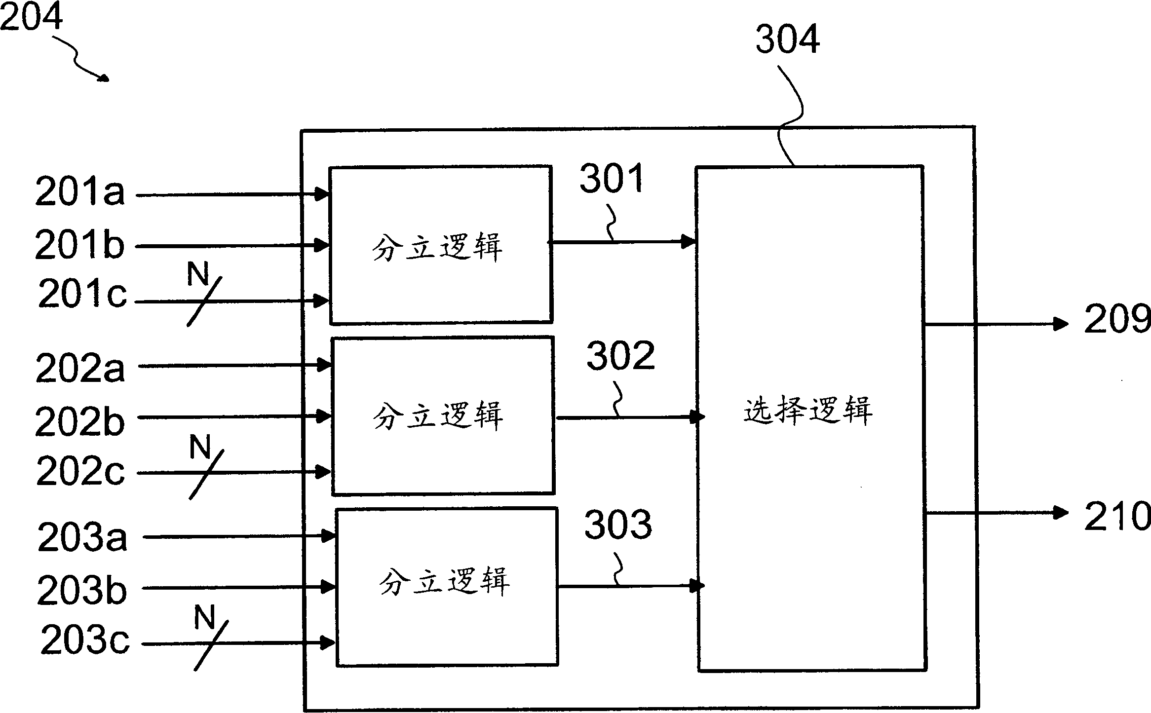
[0029] figure 2 A system preferably implemented on a single ASIC circuit is shown, comprising several hardware units 201-203, power control logic 204, and clock frequency and operating voltage control units 205 and 206. The hardware units 201 - 203 and the power control logic 204 are connected for communication via a bus 207 .

[0030] Each individual hardware unit 201 - 203 is capable of generating a first status signal 201 a - 203 a and a second status signal 201 b - 203 b which are communicated to the power control logic 204 according to the invention.

[0031] Also, the request signals 201c-203c are communicated to the power control logic 204, and the information is transferred from the power control mode register 208 to the power control logic 204. The power control mode register 208 contains information for each hardware unit 201-203 about the clock frequency and / or operating voltage to be generated for the individual hardware unit in power down mode. In other words, e...


PUM


Abstract

The invention relates to a method and device for implementing dynamic power control in an electronic system implemented on an integrated circuit, which electronic system comprises at least one or several hardware units, a hardware based power control logic substantially implemented with logic circuits, as well as a programmable power control mode register containing information about powered-down modes defined for said one or more hardware units. According to the invention, to transfer a single hardware unit from the powered-down mode to the operational mode, said hardware unit transmits to the power control logic a first level sensitive status signal for transferring said hardware unit from the powered-down mode to the wake up mode, and further a second level sensitive status signal for transferring said hardware unit from the wake up mode to the actual operating mode. Said wake up mode is characterized in that the transfer of said hardware unit from the wake up mode to the actual operational mode is now effected with a known, preferably short delay, and that the power consumption in the wake up mode is lower than in the actual operational mode. The invention makes it possible to achieve aggressive power savings.

Description

technical field [0001] According to the preamble of appended claim 1, the present invention relates to a dynamic power control method for minimizing power consumption in integrated circuits, in particular application specific integrated circuits (ASICs). The invention also relates to a power control system implementing the method according to the preamble of claim 2 attached hereto. Background technique [0002] Integrated circuits (abbreviated as ICs) are widely used to implement various electronic devices. In a large number of applications, such as in mobile stations or other small battery-operated portable devices, the power consumption of the integrated circuits contained in the device is a key factor to be considered in the design and implementation of the device. Low power consumption enables longer operating times without increasing the physical size of the device. [0003] In ASIC circuits, as well as in other integrated circuits, power consumption can be static or...

Claims


Application Information

Patent Timeline
Patent Type & Authority Applications(China)
IPC IPC(8): G06F1/32
CPCG06F1/324G06F1/3228Y02B60/1278G06F1/3203G06F1/3287G06F1/3296Y02B60/1282Y02B60/1285Y02B60/1217Y02D10/00
Inventor P·科利努米J·韦维莱宁
Owner NOKIA TECHNOLOGLES OY
Why Eureka
Try Eureka