
Storage system including plurality of storage apparatuses

a technology of storage apparatus and storage system, applied in the field of storage technology, can solve the problem that the amount of excess power could increase in proportion to the amount of consumption

Active Publication Date: 2008-01-10
HITACHI LTD
View PDF9 Cites 32 Cited by
  • Summary
  • Abstract
  • Description
  • Claims
  • Application Information

AI Technical Summary

Benefits of technology

[0008]Thus, in accordance with an aspect of the present invention, there is provided a storage system that is capable of avoiding the consumption of excess power in a storage system configured from a plurality of storage apparatuses. Further, an aspect of the present invention provides a storage system capable of inhibiting power consumption regardless of the access frequency from the host system to the storage device of the storage apparatus. Moreover, the storage system of an aspect of the present invention migrates a certain volume from a first storage apparatus having such volume accessed from the host system to a second storage apparatus, and turns off the power supply of the first storage apparatus that does not have a volume accessed from the host system.
[0013]With a storage system configured from a plurality of storage apparatuses, the present invention achieves the effect of being able to provide a storage system capable of avoiding the consumption of excess power when the host system provides business to a user.

Problems solved by technology

Therefore, with a storage system including a plurality of storage apparatuses which may consume excess power when there is no access from the host system to the storage apparatus, because the power supply circuits other than the disk apparatuses are turned on even when the disk apparatuses are turned off or in an energy saving mode, consumption of such excess power could increase in proportion to the number of storage apparatuses configuring the storage system.

Method used


Image

  • Storage system including plurality of storage apparatuses
  • Storage system including plurality of storage apparatuses
  • Storage system including plurality of storage apparatuses

Examples


first embodiment

(1) Configuration of Storage System in First Embodiment

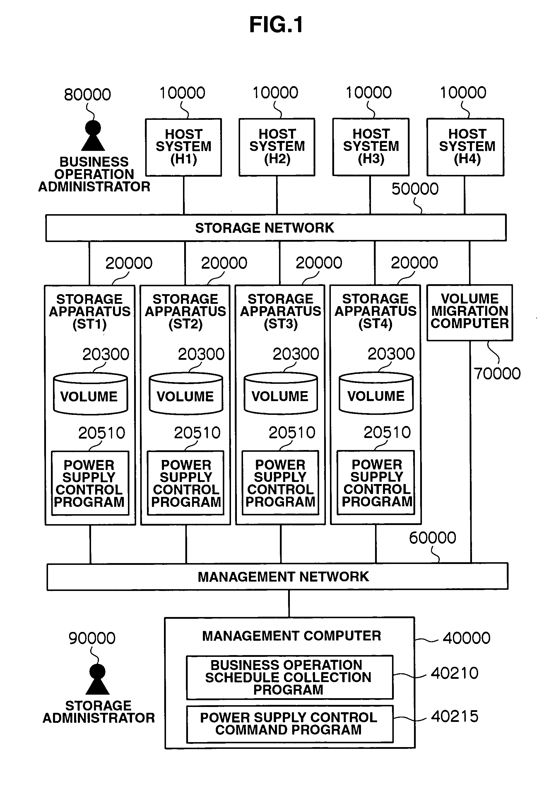
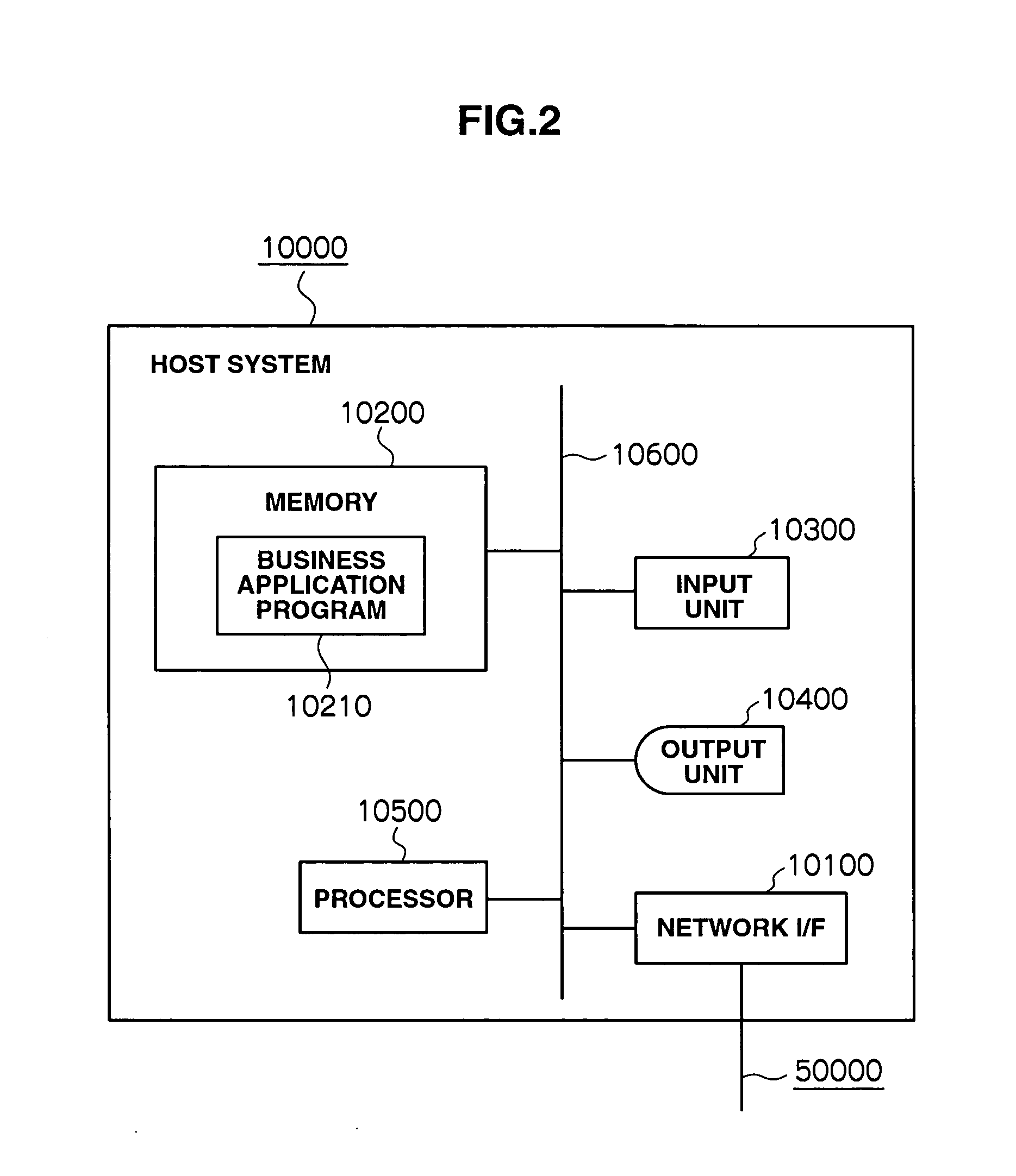
[0064]Configuration of the storage system according to a first embodiment will now be described. FIG. 1 to FIG. 6 show the configuration of the storage system and the configuration of the apparatuses connected to the storage system, and FIG. 7 to FIG. 14 show management information loaded in the respective apparatuses.

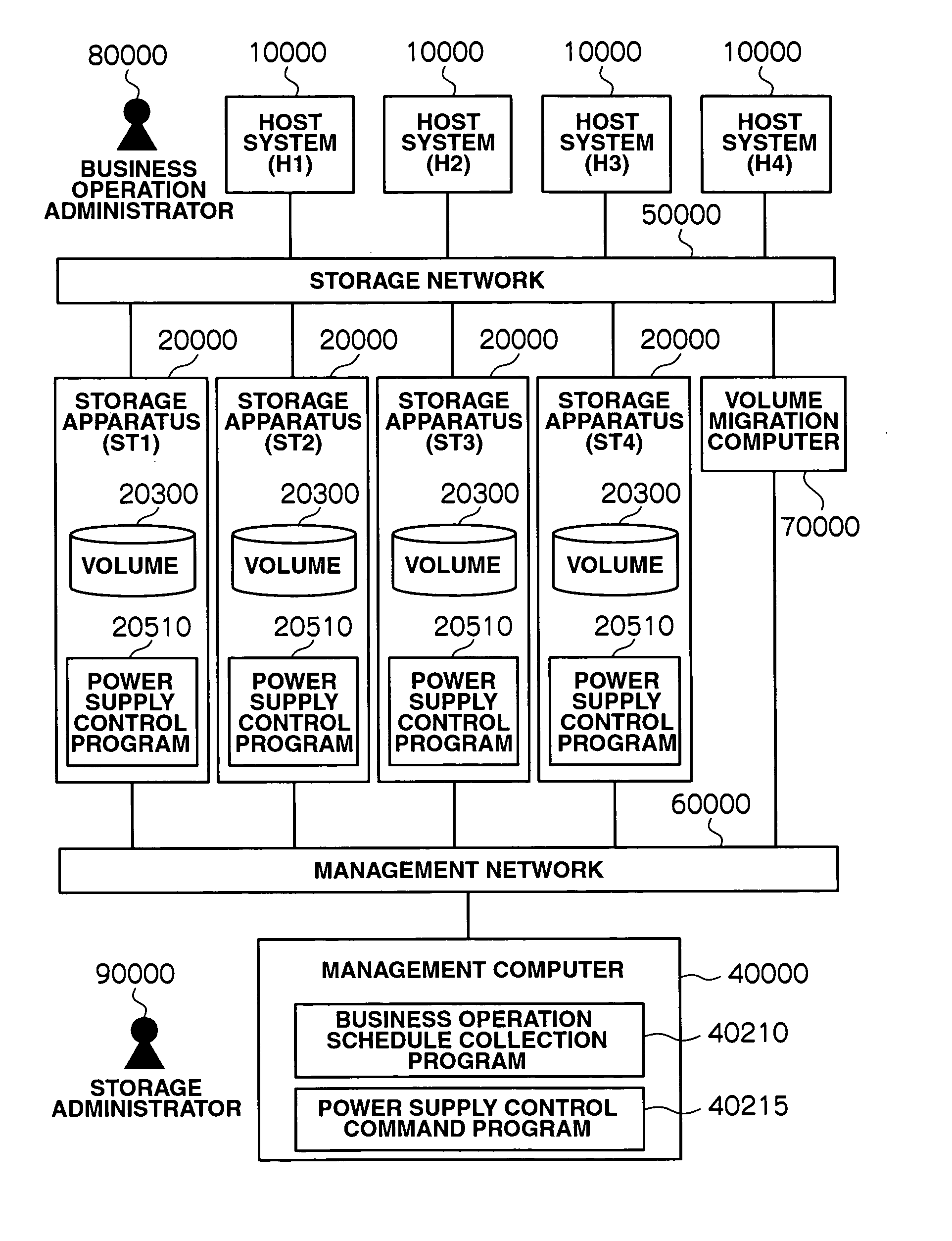
[0065]FIG. 1 shows the configuration of the storage system. The storage system is configured by one or more host systems 10000 and one or more storage apparatuses 20000 using one or more volumes 20300 being mutually connected via a storage area network 50000.

[0066]Further, a management computer 40000 for managing the storage apparatuses 20000 is connected to a plurality of storage apparatuses 20000 via a management network 60000. The storage area network 50000 is equipped with a volume migration computer 70000 for controlling the migration of volumes among the plurality of storage apparatuses 20000. The volume migr...

second embodiment

[0149]In the first embodiment, a case was described where, in a storage system configured from a plurality of storage apparatuses 20000, the volume 20300 can be migrated to or exchanged with another storage apparatus 20000, and power supply of the main power supply circuit 36000 of the storage apparatus 20000 can be turned off based on the business operation schedule using the volume 20300 in the storage apparatus. In the present embodiment, the power supply control of a storage apparatus 20000 is described in a storage system having a storage controller 30000 comprising a function of providing a volume 20300 of another storage apparatus 20000 as one's own volume 20300 to the host system 10000.

(1) Configuration of Storage System in Second Embodiment

[0150]Configuration of the storage system according to a second embodiment will now be described. FIG. 29 to FIG. 31 show the configuration of the storage system and the configuration of the apparatuses connected to the storage system, an...


PUM


Abstract

Conventionally, no consideration was given to the control of the main power supply circuit in a storage apparatus. Thus, unnecessary electric power will be consumed because it is not possible to inhibit the power consumption of the main power supply circuit of the storage apparatus. With this storage system having a plurality of storage apparatuses, a storage apparatus internally has a power supply control program for controlling the respective components and the main power supply circuit, and the power supply control command program provided to the management computer migrates a storage extent to be used for business to another storage apparatus based on the operation schedule of business to use the storage extent of the storage apparatus, and commands the power supply control of the main power supply circuit in the storage apparatuses and the respective components.

Description

CROSS-REFERENCES TO RELATED APPLICATIONS[0001]This application relates to and claims the benefit of priority from Japanese Patent Application No. 2006-187993, filed on Jul. 7, 2006, the entire disclosure of which is incorporated herein by reference.BACKGROUND[0002]1. Field of the Invention[0003]The present invention generally relates to storage technology and, more specifically, to power saving technology in storage systems, which include a plurality of storage apparatuses.[0004]2. Description of Related Art[0005]Various types of data are being handled by enterprises and individuals, and the amount data stored in storage devices is increasing rapidly due to the requirements to store electronic data for longer periods of time. Thus, in order to realize flexible scalability and reduction in management costs through uniform storage management, a storage area network configuration (primarily referred to as a SAN (Storage Area Network)) that connects a plurality of servers and a pluralit...

Claims


Application Information

Patent Timeline
IPC IPC(8): G06F17/30
CPCG06F1/3221G06F1/3268G06F3/0625Y02B60/1246G06F3/067G06F3/0689G06F3/0634Y02D10/00
Inventor NAKAGAWA, HIROTAKAASANO, MASAYASUTAGUCHI, YUICHIYAMAMOTO, MASAYUKI
Owner HITACHI LTD
Learn More