
Plasma etching gas

A technology for etching gas and plasma, applied in electrical components, semiconductor/solid-state device manufacturing, circuits, etc., to solve problems such as excessive consumption of photoresist masks

Inactive Publication Date: 2003-03-26
MACRONIX INT CO LTD
View PDF0 Cites 5 Cited by
  • Summary
  • Abstract
  • Description
  • Claims
  • Application Information

AI Technical Summary

Problems solved by technology

However, adding oxygen to the plasma etching gas will also cause excessive consumption of the organic photoresist mask, resulting in deviation of the Etching Critical Dimension (ECD) (Bias)

Method used


Image

  • Plasma etching gas
  • Plasma etching gas
  • Plasma etching gas

Examples


Embodiment Construction

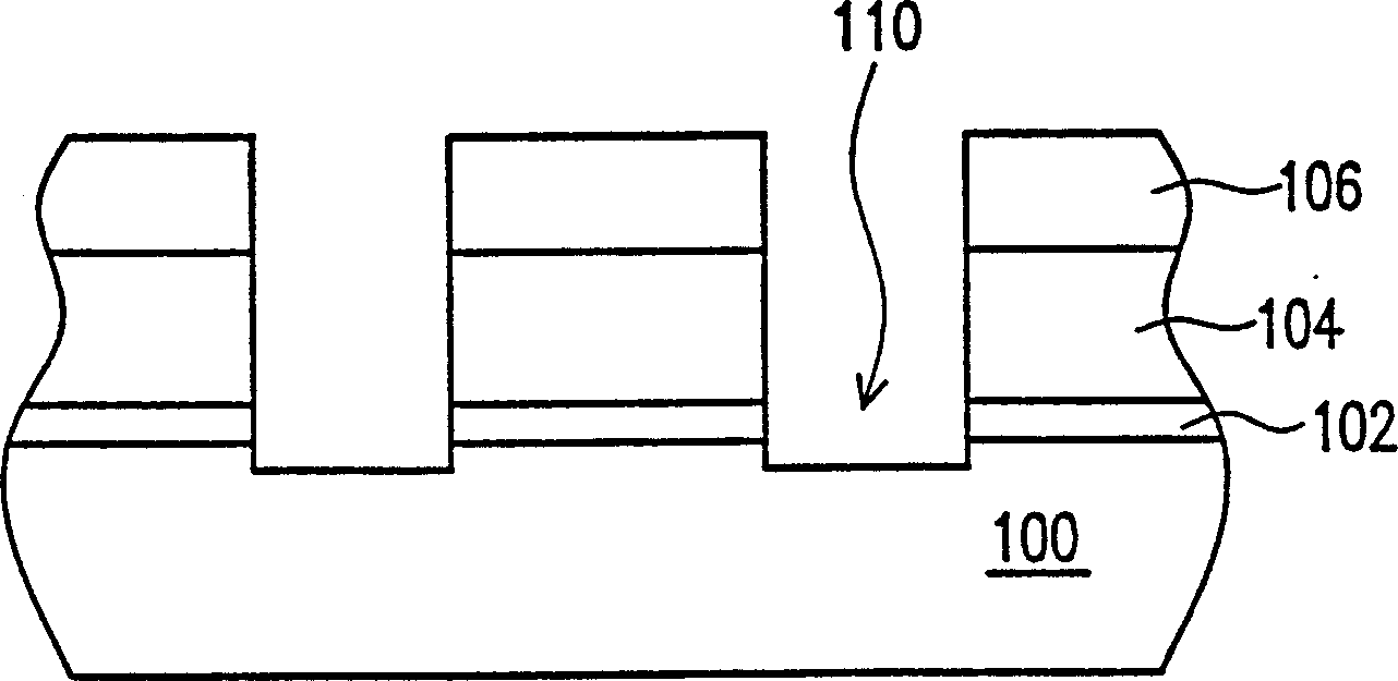
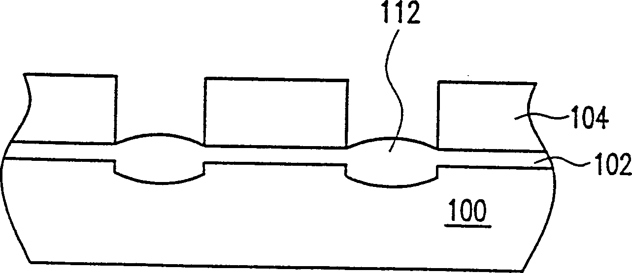
[0015] The invention provides a plasma etching gas for etching a silicon layer. Nitrogen is added to the known plasma etching gas for etching silicon oxide. The nitrogen gas makes the polymer structure deposited on the surface of the silicon layer loose and thin, so that the plasma used for etching can effectively pass through the polymer to etch the silicon layer, so that the etching uniformity of the silicon layer is increased, and at the same time it will not Excessive loss of the photoresist mask affects the etch CD. Wherein, the flow rate of adding nitrogen is 1 sccm to 50 sccm.

[0016] In the etching machine for etching silicon oxide, the etching gas used for etching the silicon oxide layer and the silicon layer includes halothane gas and argon gas. Halothane gases include fully substituted halothane gases (C x f y ) and partially substituted halothane gas (C x h y f z ). Fully substituted halothane gas (C x f y ), such as carbon tetrafluoride (CF 4 ), carbon ...


PUM


Abstract

The gas is suitable for the etching machine of etching silicon oxide to etch silicon layer. The gas at least includes the partial substitutional halothane gas, the entire substitutional halothane gas, argon gas and nitrogen gas. The ratio between the partial substitutional halothane gas and the entire substitutional halothane gas is about 3:1 to 15:1.

Description

technical field [0001] The present invention relates to an etching process for an integrated circuit (Integrated Circuit, IC), and in particular to a plasma etching gas. Background technique [0002] Today, with the vigorous development of integrated circuits, the miniaturization and integration of components is an inevitable trend, and it is also an important topic for active development in all walks of life. Among them, the etching process plays a very important role from the front end to the back end of integrated circuit manufacturing, and often constitutes a key technology with the lithography process. The etching process can be divided into two types, one is wet etching technology, and the other is dry etching technology. Compared with wet etching, dry etching technology has the advantages of low cost, high yield and anisotropic etching, so it has become an indispensable technology in the current integrated circuit process. [0003] At present, semiconductor componen...

Claims


Application Information

Patent Timeline
IPC IPC(8): H01L21/3065
Inventor 梁明中
Owner MACRONIX INT CO LTD
Learn More