
Melt near quick setting method and special apparatus

A special equipment and melt technology, which is applied in the field of near-rapid solidification of melt and special equipment, can solve the problems of insufficient smoothness of the sample surface, complex die-casting technology, and reduced cooling rate, etc., and achieve good filling effect, high density value, Effect of reducing jet resistance

Inactive Publication Date: 2003-03-12
INST OF METAL RESEARCH - CHINESE ACAD OF SCI
View PDF0 Cites 27 Cited by
  • Summary
  • Abstract
  • Description
  • Claims
  • Application Information

AI Technical Summary

Problems solved by technology

Among them, the melt water quenching method is to quench the molten master alloy into the cooling medium. The method is simple, but due to the resistance of the cooling medium, the cooling rate is low; the copper mold suction casting method is to directly cast the molten master alloy into the metal In the mold, due to the rapid solidification of the master alloy melt in the copper mold, the surface of the sample shrinks to form a gap with the inner cavity of the mold, resulting in a decrease in the cooling rate, resulting in a smooth surface of the sample; in addition, the die-casting method is complex and difficult to operate. The cost is high; the directional solidification method is suitable for making rods, but not for special-shaped parts; the deep supercooling method is suitable for making some smaller samples, and there are certain limitations on the sample size requirements

Method used


Image

  • Melt near quick setting method and special apparatus
  • Melt near quick setting method and special apparatus
  • Melt near quick setting method and special apparatus

Examples


Embodiment 1

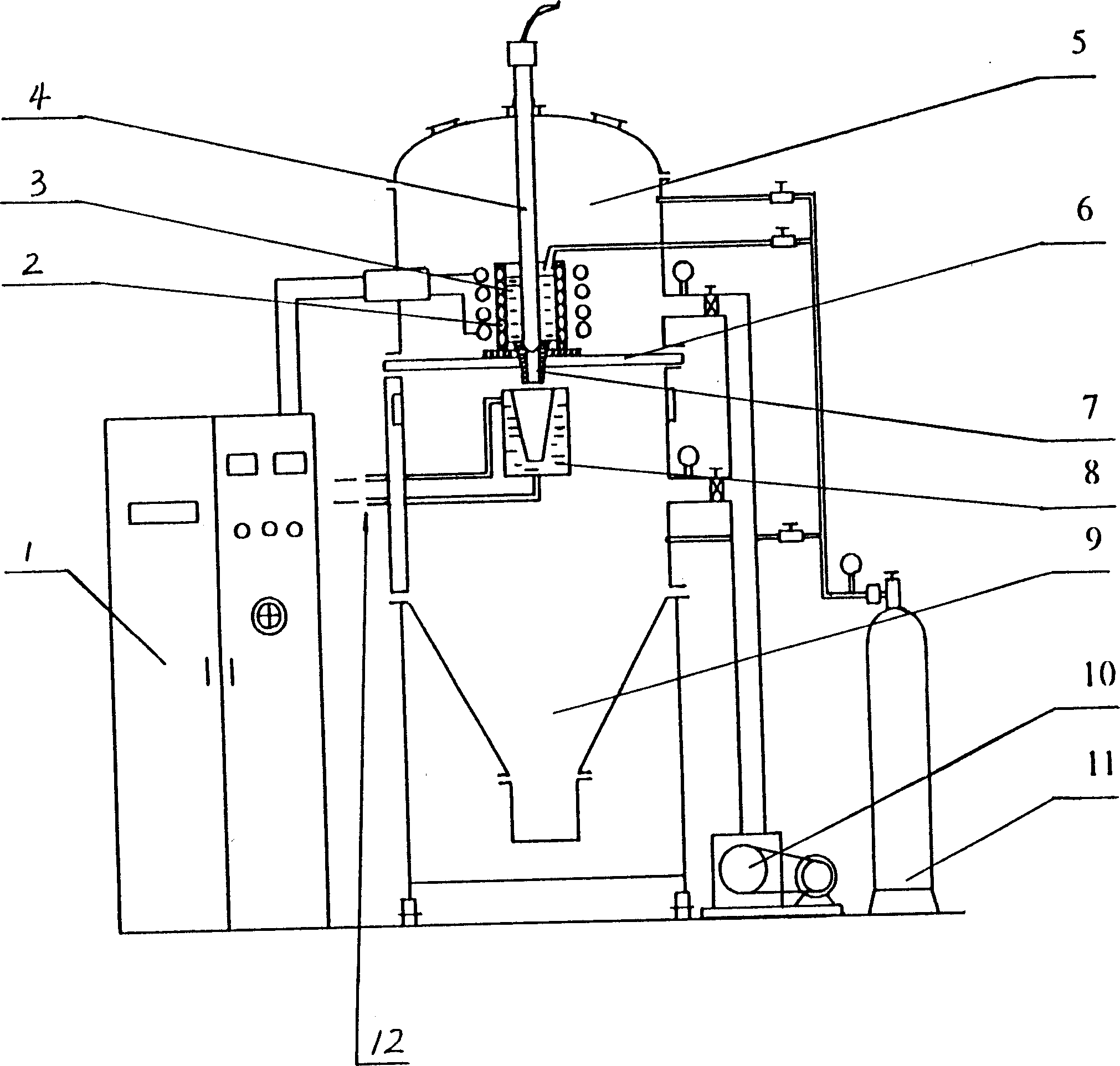
[0026] The composition and atomic percentage of Zr-Cu-Ni-Al master alloy are: Zr 55 Cu 30 Ni 5 Al 10 , heating in a medium frequency induction furnace under vacuum conditions, the specific steps are as follows:

[0027] 1. Plug the guide tube with a plunger rod, and add the master alloy into the quartz crucible in the vacuum chamber;

[0028] 2. Start the vacuum device and the inflation device, repeatedly evacuate the upper and lower vacuum chambers and fill them with argon gas twice, and keep the vacuum degree at 5×10 -3 Pa;

[0029] 3. Start the intermediate frequency induction furnace and heat the master alloy to a temperature 100-120°C higher than the melting point;

[0030] 4. Pull up the plunger rod that blocks the crucible, inject positive pressure argon gas (its purity is 99.999%) above the melt for spray casting, the blowing pressure is 0.1MPa, and at the same time, the lower part of the alloy melt is subjected to high vacuum suction casting, The alloy melt is i...

Embodiment 2

[0033] The difference from Example 1 is:

[0034] The Zr-Cu-Ni-Al master alloy is heated in a medium frequency induction furnace under vacuum conditions, and the vacuum degree is 1×10 -3 Pa, when the melting point of the alloy is 50-80°C, the plunger is pulled out, the blowing pressure is 0.05MPa, the operation is the same as in Example 1, and an amorphous / nanocrystalline composite material with nanocrystalline precipitated phases in the amorphous matrix is ​​prepared .

Embodiment 3

[0036] The difference from Example 1 is:

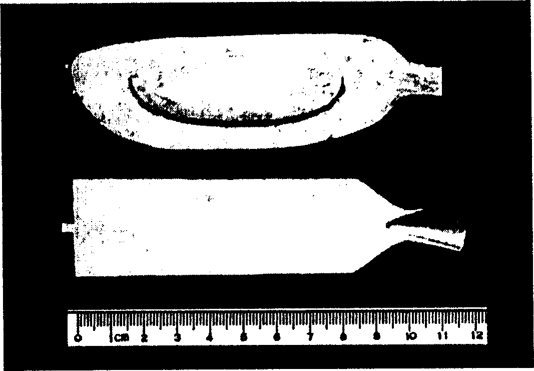
[0037] The operating conditions are the same as in Example 1. According to the shape of the mould, a large-scale plate of 30 × 4 × 100 (mm) and a golf racket head are inlaid with amorphous alloy special-shaped parts, such as figure 2 shown.


PUM

PropertyMeasurementUnit
Diameteraaaaaaaaaa

Abstract

A near-fast solidifying method and apparatus for molten body are disclosed. Said apparatus is composed of a vacuum chamber consisting of upper and lower vacuum cavities and central sealing unit, heater in the upper vacuum cavity, quartz crucible in the heater, mould in the lower vacuum cavity, and circulating cooler. Its method includes vacuumizing said vacuum chamber repeatedly, filling argon gas, heating mother alloy to a temp which is 50-200 deg.C higher than its melting point, pulling up plunger rod while filling pressure argon gas to pour the molten alloy in mould instantaneously, and quick cooling.

Description

technical field [0001] The invention relates to melt solidification technology, in particular to a melt near-rapid solidification method and special equipment. Background technique [0002] Bulk amorphous alloys, nanocrystalline alloys, materials prepared by semi-solid processing, etc. are contemporary new materials. Due to their special structure, they have excellent mechanical, physical and chemical properties, and have received close attention in the fields of materials science and engineering. , and has broad application prospects. [0003] Under the condition that the alloy components and their content ratio are determined, the key to the rapid solidification of alloy melts to prepare amorphous alloy bulk materials is the cooling rate of the melt, the pre-stored crystal nuclei in the melt, and the cooling medium (such as a crucible) , mold) caused by heterogeneous nucleation, most of the melt cooling rate of the preparation of bulk amorphous alloys is near rapid solidi...

Claims


Application Information

Patent Timeline
IPC IPC(8): B22D25/06
Inventor 张海峰丁炳哲王爱民李宏胡壮麒
Owner INST OF METAL RESEARCH - CHINESE ACAD OF SCI
Learn More