
Spiral electrode group winding method and device and battery using them

A technology of winding device and electrode group, applied in the direction of assembling battery machine, non-aqueous electrolyte storage battery, aqueous electrolyte battery, etc. Stable and excellent production performance

Inactive Publication Date: 2002-12-25
GK BRIDGE 1
View PDF2 Cites 21 Cited by
  • Summary
  • Abstract
  • Description
  • Claims
  • Application Information

AI Technical Summary

Problems solved by technology

At this time, although the volume efficiency of the electrode group occupied in the battery case is excellent, due to the pulsation of the winding peripheral speed of the winding core, winding deviation is likely to occur, and the flat cross-sectional winding core is wound from the It is difficult to remove the electrode group, and because there is no remaining separator and space, the liquid retention performance when injecting the electrolyte is deteriorated

Method used


Image

  • Spiral electrode group winding method and device and battery using them
  • Spiral electrode group winding method and device and battery using them
  • Spiral electrode group winding method and device and battery using them

Examples


Embodiment Construction

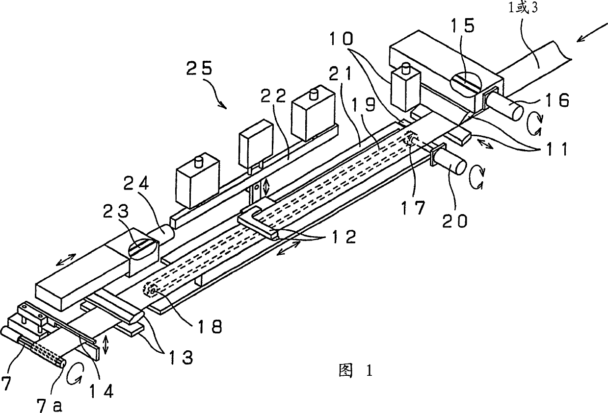
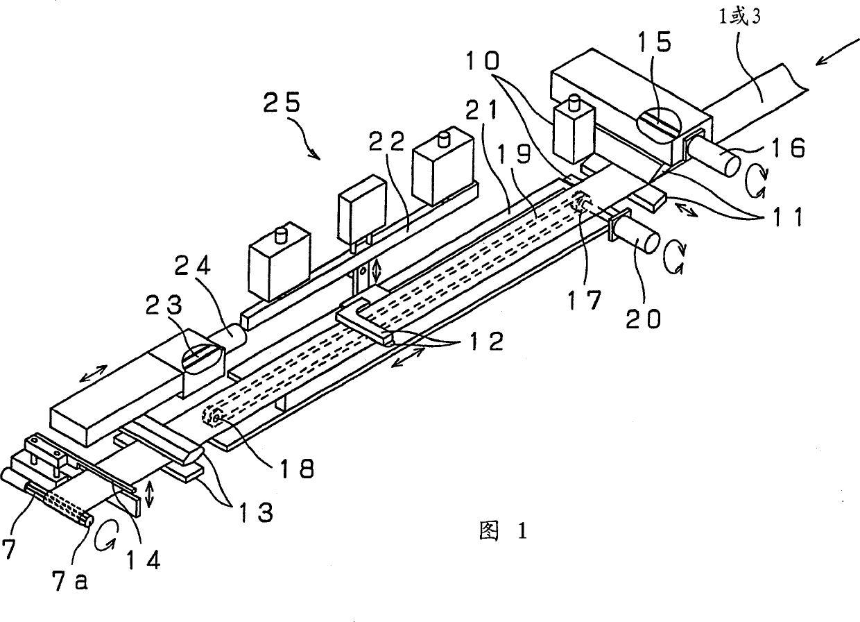
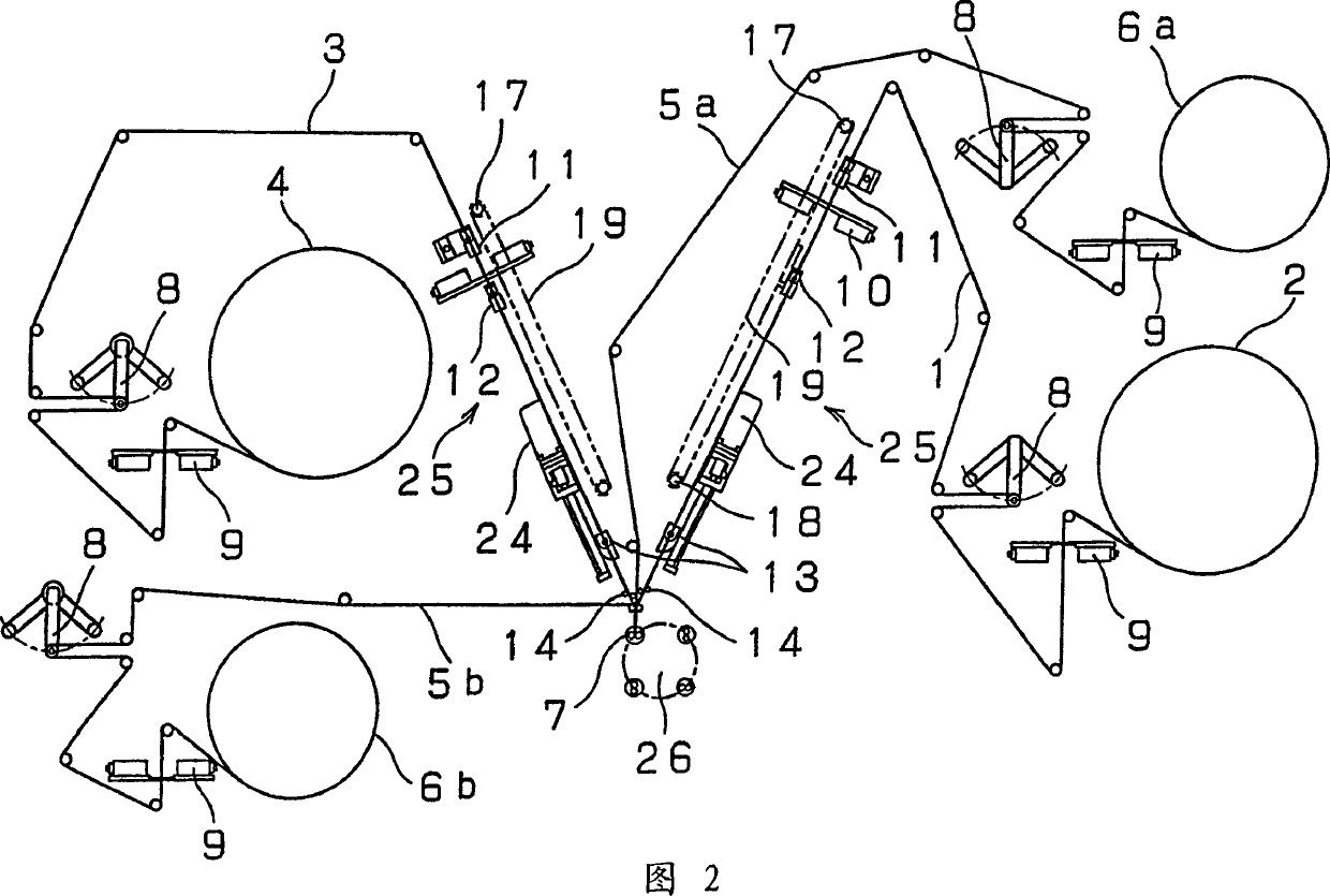
[0031] The embodiment of the winding method and device thereof for the battery spiral electrode group of the present invention is described below with reference to the accompanying drawings. The perspective view of the main part in the case (however, for the sake of understanding, only the positive electrode plate 1 or the negative electrode plate 3 is wound on the winding core 7, and other electrode materials are omitted to simplify the illustration). Fig. 2 is a diagram showing a schematic configuration of a winding device for a battery spiral electrode group according to the present invention.

[0032] In FIG. 2 , the positive and negative electrode plates 2 and 4 , the first separator plate 6 a and the second separator plate 6 b wound in rolls are respectively installed on a supply conveying shaft (not shown). And the winding device part is installed on a rotating disk 26, as shown in Figure 4, four axially perpendicular cross-sections are made into substantially hexagonal...


PUM


Abstract

The present invention provides a method and device for winding a spiral electrode group for a battery. The method and device wind a continuous strip-shaped positive electrode, negative electrode plate, and separator into a spiral electrode group through a freely rotatable winding core. The edge position of the strip-shaped electrode plate is detected by the edge position detection device at a predetermined position near the winding core, and compared with the reference position, and according to the result, it is grasped by the chuck movable from the electrode plate to the direction perpendicular to the direction of travel of the electrode plate. , after correcting the edge position of the electrode plate, the electrode plate is held by the gripper that is constrained by the guide rail to move only in the direction parallel to the transfer direction of the electrode plate, and the electrode plate is held by the third chuck, and the front end of the electrode plate is supplied to the winding core , The second chuck prevents the positional deviation of the electrode plate and winds the electrode group while applying tension to the electrode plate, thereby performing electrode plate winding with a small deviation in the winding of the electrode group. In addition, the flatness of the electrode during flat shaping can be improved by making the cross-sectional shape of the winding core at right angles to the axial direction substantially hexagonal.

Description

technical field [0001] The present invention relates to a winding method and device for a battery electrode group manufactured by overlapping the positive and negative plates of the battery through a separator and winding them in a spiral shape such as a lithium rechargeable battery, a nickel-hydrogen battery, and a battery containing the electrode group . Background technique [0002] Hitherto, as the structure of mass-produced small high-capacity rechargeable batteries, each electrode material such as a positive electrode plate, a negative electrode plate, and a separator made into a strip shape is generally overlapped and wound into a spiral electrode group. The positive and negative electrode plates are dried by filling the conductive core material with active material as the main component paste, and then rolling processing is performed to adjust the thickness of the electrode plate and increase the density of the active material layer, and then use shearing Machine cu...

Claims


Application Information

Patent Timeline
Patent Type & Authority Applications(China)
IPC IPC(8): H01M6/10H01M10/04H01M10/052H01M10/34
CPCH01M10/0409H01M10/052H01M10/345Y02E60/10Y10T29/49108Y02P70/50H01M10/04
Inventor 石川昭久田中康史中之濑武治大泽善树
Owner GK BRIDGE 1
Learn More