
System for testing optical environment by image processing technique

A technology of image processing and light environment, which is applied in the field of optical measurement, can solve the problems of inability to quantify the cause and effect of data, less information, poor precision, etc., and achieve the effects of stable carrier, high sensitivity and easy operation

Inactive Publication Date: 2002-07-03
TIANJIN UNIV
View PDF0 Cites 24 Cited by
  • Summary
  • Abstract
  • Description
  • Claims
  • Application Information

AI Technical Summary

Problems solved by technology

[0003] The purpose of the present invention is to overcome and solve the separation of shape, color and quantity in the existing architectural light environment research and testing process; the data cause and effect cannot be quantified and extracted; Architectural light environment test and research system based on digital image processing technology and light environment research theory

Method used

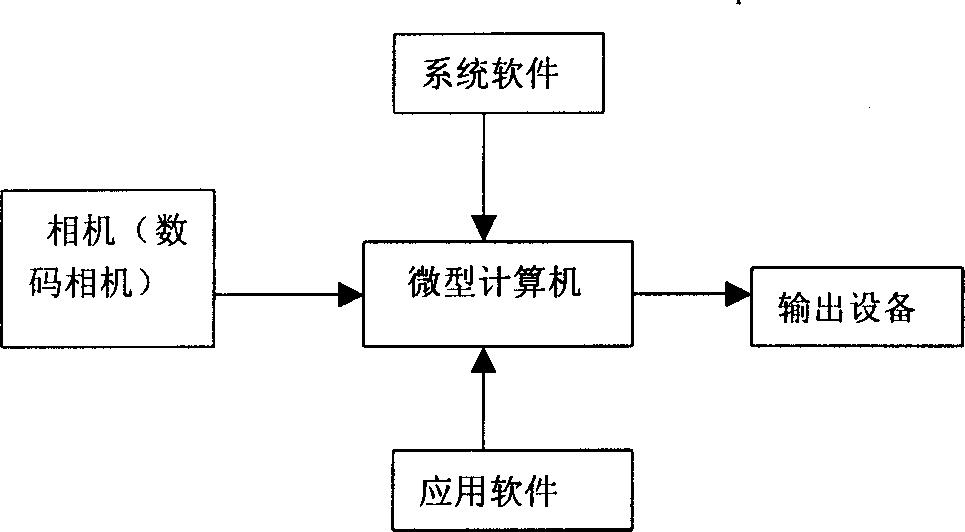
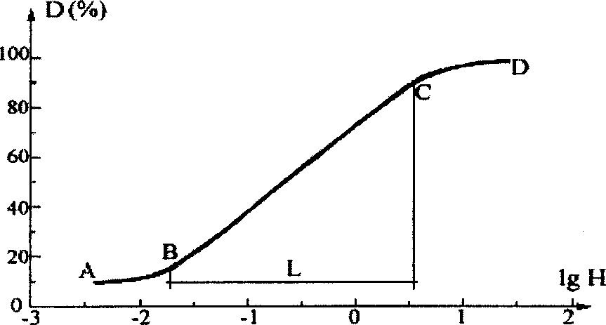
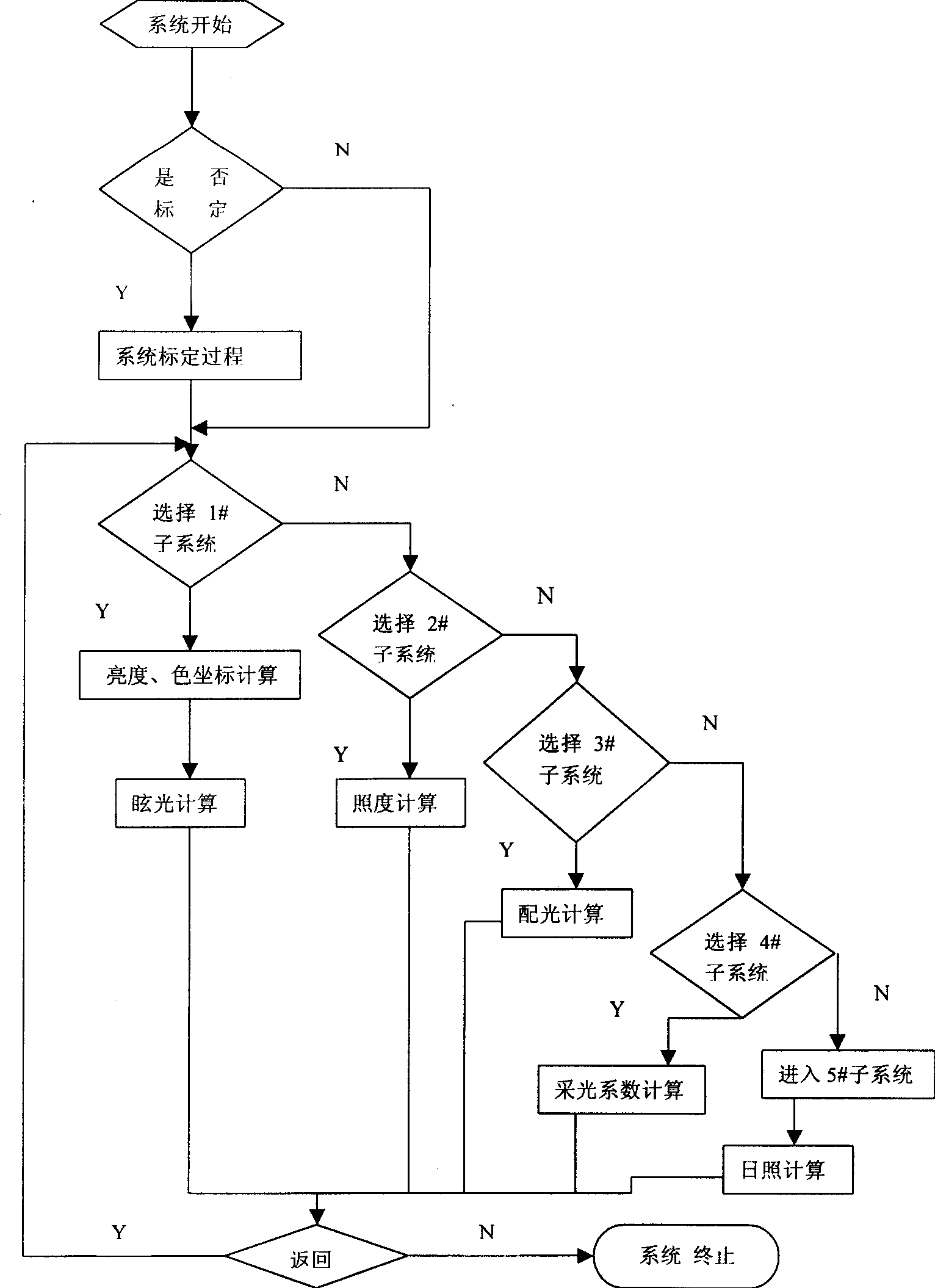

Image

  • System for testing optical environment by image processing technique
  • System for testing optical environment by image processing technique
  • System for testing optical environment by image processing technique

Examples


specific Embodiment approach

[0027] DETAILED DESCRIPTION OF THE PREFERRED EMBODIMENTS The present invention will be further described below in conjunction with the principles and accompanying drawings:

[0028] (1) Calibrate the camera: Before the test, the digital camera needs to be calibrated. 65 The image of the standard color card under the light source, and then use the color coordinates of the standard color plate to calibrate the color coordinates of the color plate in the image. Read the R, G, and B values ​​of the image through the prepared image processing software or use some commercial image processing software (such as PHOTOSHOP, etc.), and find out the relationship between the R, G, and B values ​​and the CIE color stimulus value XYZ value:

[0029] X=a1R+b1G+c1B

[0030] Y=a2R+b2G+c2B

[0031] Z=a3R+b3G+c3B (1) where a1, b1, c1, a2, b2, c2, a3, b3, c3 are calibration coefficients. Among them, the image gray value D is equal to the color coordinate Y value, s...


PUM


Abstract

A system using image processing technique to test the optical environment of building features that all the optical information in the environment is taken by camera and then input to cmputer, where each pixel on computer image is used as a test point to find the relation between its gray level and RGB value and the brightness and colourity of object point. The analyzed result is stored. Its test software is also disclosed.

Description

technical field [0001] The invention relates to an optical measurement method, in particular to a method for testing light environment by using image processing technology. Background technique [0002] Light is very important in people's living environment, and it will directly affect people's vision, health, safety, work efficiency and psychological status and so on. Such as: the quality of the light environment in the classroom directly affects the students' vision and learning effect; the quality of the light environment on the outdoor road affects the safety of driving; Artistic effect of cityscape. How should the light environment be designed to achieve a positive impact? This has been the main research content in the field of architectural optics. In order to achieve the purpose of research, the light environment must be quantified, and the quantified data can become the scientific basis for designing and evaluating the light environment. In the past, pho...

Claims


Application Information

Patent Timeline
IPC IPC(8): G01J1/00G01J1/52G01J3/52G01N21/00
Inventor 沈天行
Owner TIANJIN UNIV
Learn More