Method for preparing low hydroxy content optical-fiber precast rod by tubular CVD process

A chemical vapor deposition, optical fiber preform technology, applied in the field of optical fiber manufacturing, can solve the problems of increased OH absorption peak, difficult to achieve anhydrous peak fiber loss, failure to use and other problems

Inactive Publication Date: 2007-08-08
JIANGSU FASTEN CO LTD
View PDF3 Cites 0 Cited by
  • Summary
  • Abstract
  • Description
  • Claims
  • Application Information

AI Technical Summary

Problems solved by technology

However, the commonly used wavelength range is only about one-third of the theoretical value, which is mainly caused by the water absorption peak at 1385nm.
[0003] Silica single-mode fiber has a hydroxyl absorption peak near the wavelength of 1385nm, as long as there are a few ppb (parts per billion) hydroxyl groups inside the fiber, it is enough to cause a few decibels of attenuation near 1385nm, making it about 100nm wide in 1350-1450nm The attenuation in the frequency spectrum is about 1dB / km, so the fifth band with a width of 180nm has not been used, and the sum of the second, third and fourth bands currently in use is only 160nm
The first type is OH-type loss, the hydrogen reaction between the residual hydrogen gas and various silicon or germanium defects in the optical fiber will form SiOH and GeOH absorption peaks during the installation and use of the optical cable, and its center wavelength is exactly at 1385nm, which leads to an increase in the fiber loss absorption peak
The second type is the SiH type loss, which occurs at 1530nm, and is often accompanied by an increase in the OH absorption peak at 1385nm
[0016] After using high-purity raw materials, high-purity gas and high-purity silica substrate, the hydroxyl content in the fiber can be well controlled, but it is still difficult to meet the requirement of an anhydrous peak fiber with a loss of less than 0.31dB / km at 1385nm

Method used


Image

  • Method for preparing low hydroxy content optical-fiber precast rod by tubular CVD process
  • Method for preparing low hydroxy content optical-fiber precast rod by tubular CVD process

Examples


Embodiment Construction

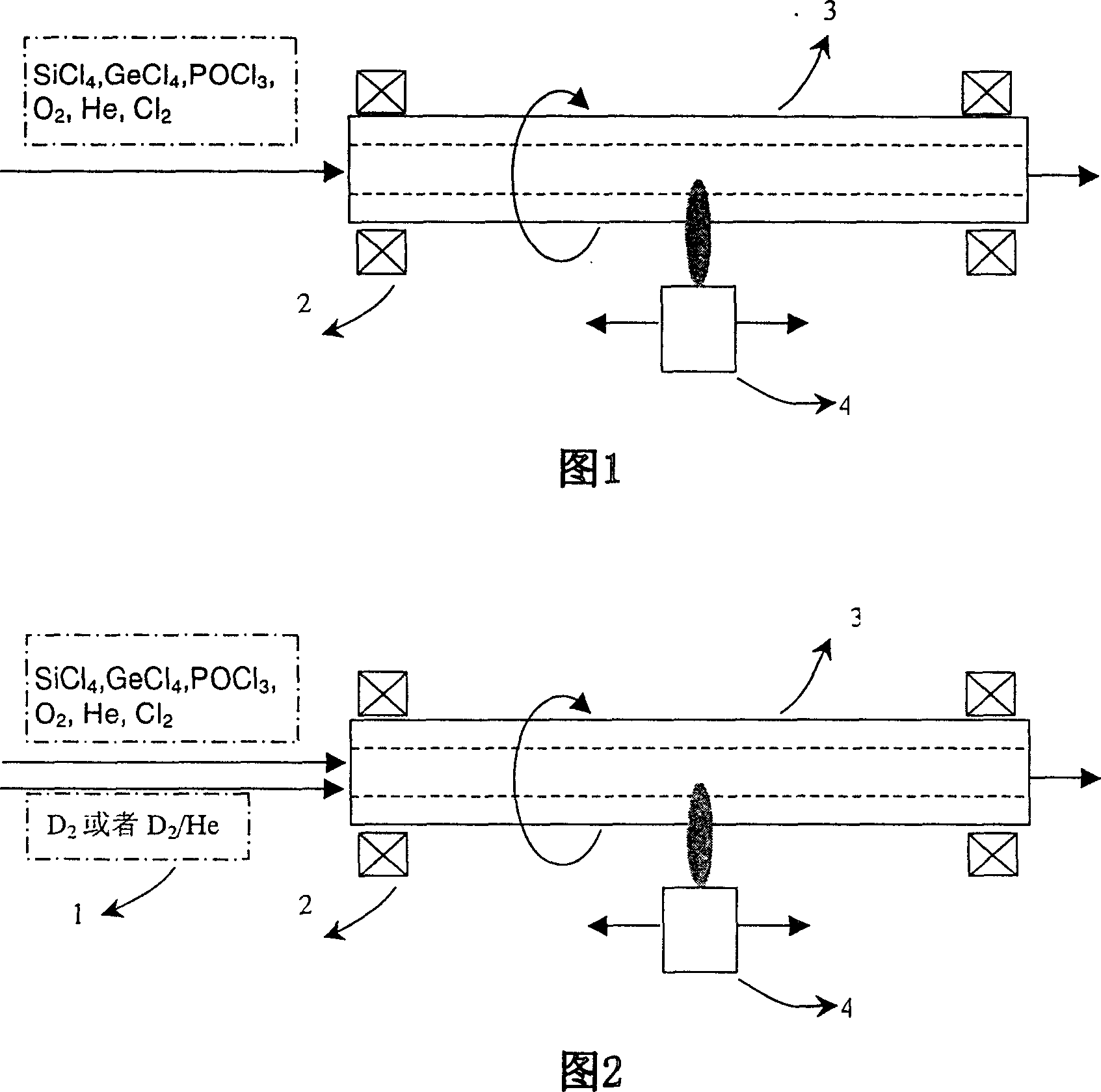
[0043] The method of preparing optical fiber preform by ordinary MCVD process is shown in Figure 1: First, deposit cladding and core layers from the inner wall to the center inside the pure silica substrate tube, and then place the deposited quartz glass at a high temperature of 2100-2300°C Melted into a solid mandrel. In order to increase the hydrogen-deuterium replacement process, it is necessary to improve the ordinary MCVD lathe and process to a certain extent.

[0044] The present invention is a corresponding improvement on the traditional MCVD process, and its specific implementation is according to the process and device shown in Figure 2 .

[0045] A deuterium gas storage and purification system and delivery system 1 are added in front of the intake end of a common MCVD lathe. The purified deuterium gas enters the quartz tube on the MCVD lathe through its delivery system, and the flow of deuterium gas is controlled by an accurate mass flow meter. There are many ways ...


PUM


Abstract

The invention is a method to prepare low-hydroxy content optical-fiber precast stick by in-tube chemical vapor-phase deposition process, introducing hydrogen isotope displacement process into traditional MCVD or PCVD process, when preparing optical fiber precast stick by MCVD orPCVD process, using deuterium to displace the hydrogen in base tube and deposition layer, during preparing, discontinuously using deuterium to displace the hydrogen in base tube and deposition layer again and again, where the displacement process is that: charging helium or nitrogen gas in the base tube to drive out the oxygen, then stopping charging, starting charging deuterium gas or mixed gas of deuterium and nitrogen gases to displace the hydrogen in a certain depth of the base tube from inner surface to outside; stopping charging deuterium gas, but charging helium gas or nitrogen gas to drive out the mixed gas of hydrogen gas and deuterium gas in the base tube, and starting raising the temperature; then stopping charging helium or nitrogen gas, and starting the feeding gas and auxiliary gas carrying raw material. It can obtain low-hydroxy content optical-fiber precast stick and optical fiber.

Description

1. Technical field [0001] The present invention relates to a low-hydroxyl content optical fiber preform made by using an in-tube chemical vapor deposition method combined with a hydrogen isotope replacement process, in particular to a method for preparing a low-hydroxyl content optical fiber preform by MCVD and PCVD and other in-tube chemical vapor deposition processes. Thereby, the technological method for obtaining low water peak or no water peak optical fiber belongs to the field of optical fiber manufacturing. 2. Background technology [0002] The wavelength of light that can be transmitted by silica single-mode fiber is limited by the cut-off wavelength of the single-mode fiber (about 1260nm) at the short-wavelength end, and is limited by the intrinsic absorption of the silica material of the fiber itself at the long-wavelength end. If the working wavelength exceeds 1650nm , the far-infrared absorption loss in the intrinsic absorption will increase rapidly, so the theor...

Claims


Application Information

Patent Timeline
Patent Type & Authority Patents(China)
IPC IPC(8): C03B37/018
Inventor 迟玉山刘礼华卞进良
Owner JIANGSU FASTEN CO LTD
Why Eureka
Try Eureka