
Turbine blade and method for producing turbine blade

A technology for turbine blades and blades, applied in the fields of turbine blades and manufacturing turbine blades, can solve problems such as inability to guarantee cooling, and achieve the effects of reducing redesign time, lowering material costs, and simplifying the manufacturing process

Inactive Publication Date: 2007-04-25
SIEMENS AG
View PDF2 Cites 0 Cited by
  • Summary
  • Abstract
  • Description
  • Claims
  • Application Information

AI Technical Summary

Problems solved by technology

However, its disadvantage is that this throttle has a considerable loss coefficient, which leads to flow separation in the cooling gas inlet area, so that a sufficient cooling in this area of ​​the turbine blade cannot be guaranteed.

Method used


Image

  • Turbine blade and method for producing turbine blade
  • Turbine blade and method for producing turbine blade
  • Turbine blade and method for producing turbine blade

Examples


Embodiment Construction

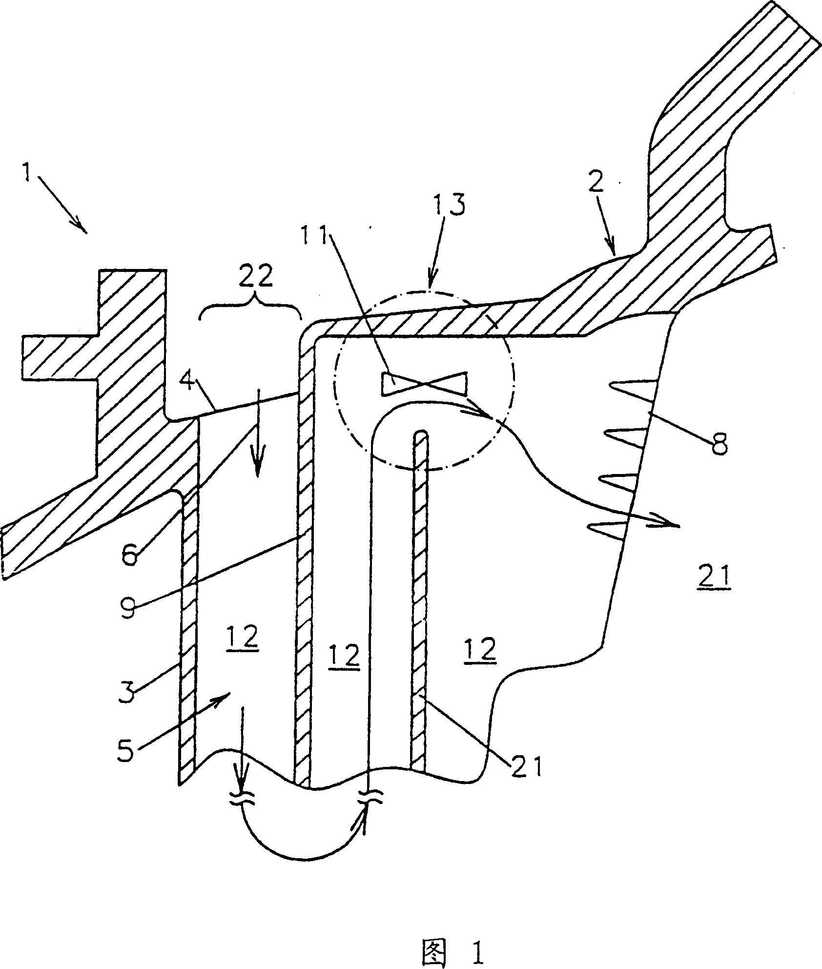
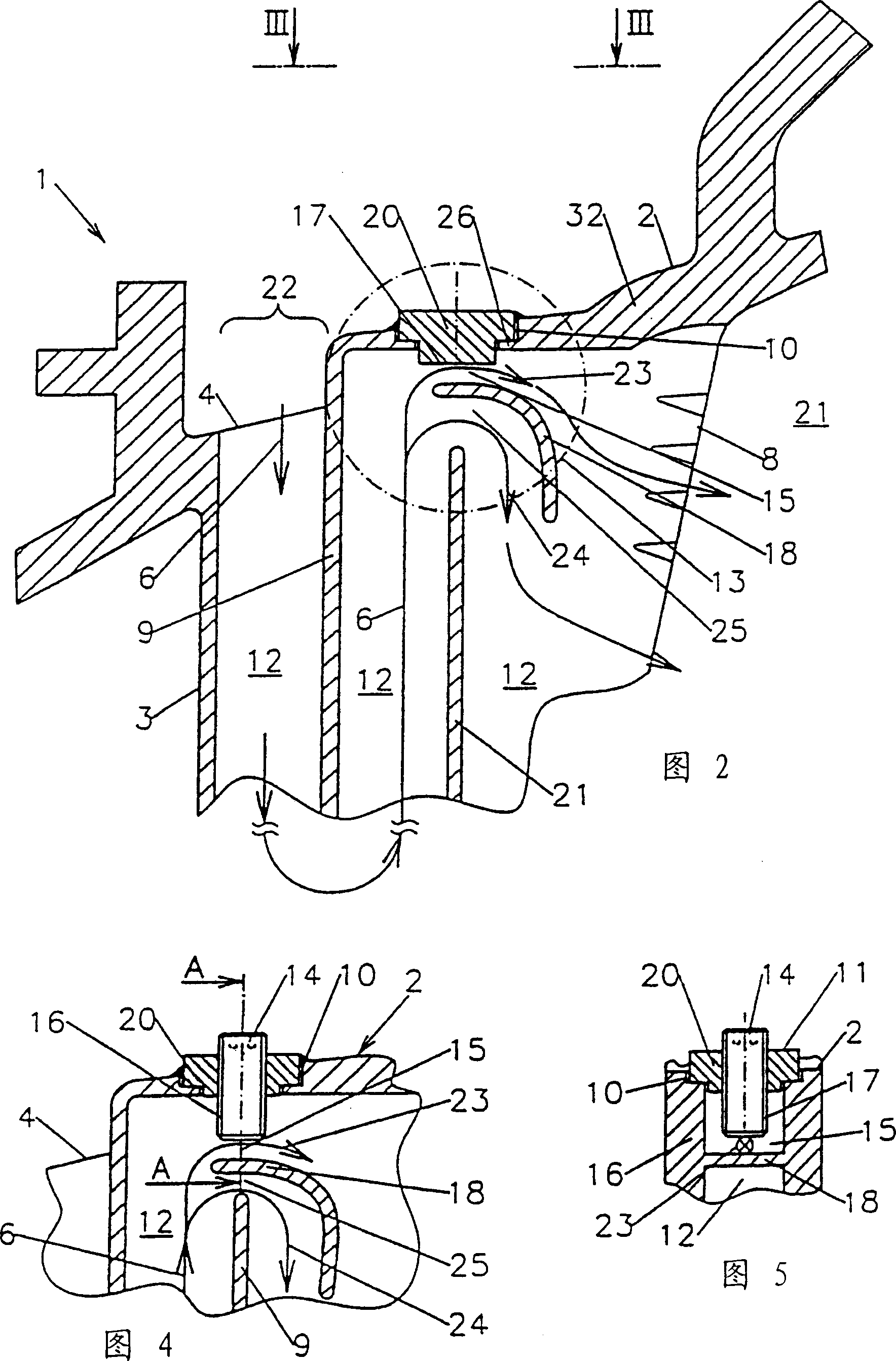
[0028] FIG. 1 shows a longitudinal section through the root region 2 and part of the channel system 5 of a gas-cooled turbine blade 1 . The channel system 5 is mainly located in the blade region 3 of the turbine blade 1 . It has an inlet hole 22 in the root region 2 at the beginning of the cooling gas flow path 6 and an outlet hole 8 in the outflow region 21 of the turbine blade 1 through which the cooling gas is introduced into the channel system 5 and through which outlet The bore 8 leaves the channel system 5 at the end of its flow path 6 . In its flow path 6 , the cooling gas is led in a meandering manner through the channels 12 separated from each other by partitions 21 , from the root region 2 to the not-shown top region and back to the root region 2 several times. These channels 12 communicate back and forth with each other through turn-back points 13 adjacent to the root zone 2 or the top zone. A throttle 11 influencing the cooling gas flow is located in the rear secti...


PUM


Abstract

The invention relates to a turbine blade (1), in particular, a gas turbine blade, comprising a head, a foot (2) and a blade section (3), in addition to an internal canalisation system (5) consisting of individual channels (12), through which coolant gas can pass along a flow path (6) within the turbine blade (1). Said turbine blade also comprises a throttle device (11) which influences the passage of the coolant gas without impairing the flow of the coolant gas in the intake area. The invention is characterised in that the throttle device (11) located in the rear section of the flow path (6) is positioned upstream of the exit openings (8).

Description

technical field [0001] The present invention relates to a turbine blade, in particular a gas turbine blade, with a top region, a root region and a blade region, and with a plurality of flow channels for cooling gas into the interior of the turbine blade A system of internal passages consisting of passages in which the cooling gas travels from the root region through the blade region to the top region and then reverses in the opposite direction, and a throttle that affects the flow of the cooling gas There is also an outlet hole arranged on the outflow side of the turbine blade for leading the cooling gas out of the turbine blade; the invention also relates to a method for manufacturing a turbine blade. Background technique [0002] In order to achieve high efficiency during operation of a turbine driven by a reaction fluid, in particular a gas turbine driven by gas, the reaction fluid is heated to a high temperature. In a gas turbine with a combustion chamber that generates...

Claims


Application Information

Patent Timeline
IPC IPC(8): F01D5/18F01D9/02F02C7/00F02C7/18
CPCF01D5/18F01D5/187B22C9/10B22C21/14Y10T29/49339Y10T29/49341
Inventor 德克·安丁迈克尔·肖伊尔伦彼得·蒂曼
Owner SIEMENS AG
Learn More