Topical coating with foil

A technology of coating and carrier foil, which is applied in the field of partial coating with foil, can solve the problems of increasing the investment cost and space consumption of printing factories, and achieve the effect of flexible processing and stable composition

Active Publication Date: 2015-09-30
HEIDELBERGER DRUCKMASCHINEN AG
View PDF4 Cites 0 Cited by
  • Summary
  • Abstract
  • Description
  • Claims
  • Application Information

AI Technical Summary

Problems solved by technology

However, in order to use this method and this device it is necessary to provide an additional laminating device, which on the one hand increases maintenance, takes up space and on the other hand increases the investment costs of the printing plant

Method used


Image

  • Topical coating with foil
  • Topical coating with foil
  • Topical coating with foil

Examples


Embodiment Construction

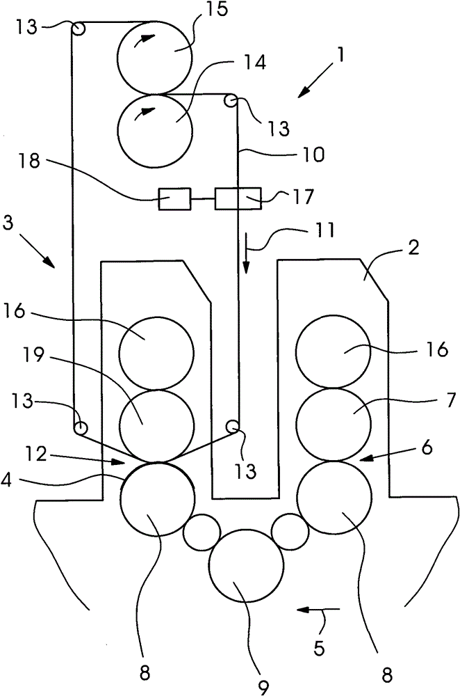
[0027] figure 1 A partial view of a lamination device 1 with an application unit 2 and a lamination unit 3 is shown.

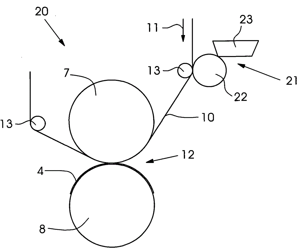
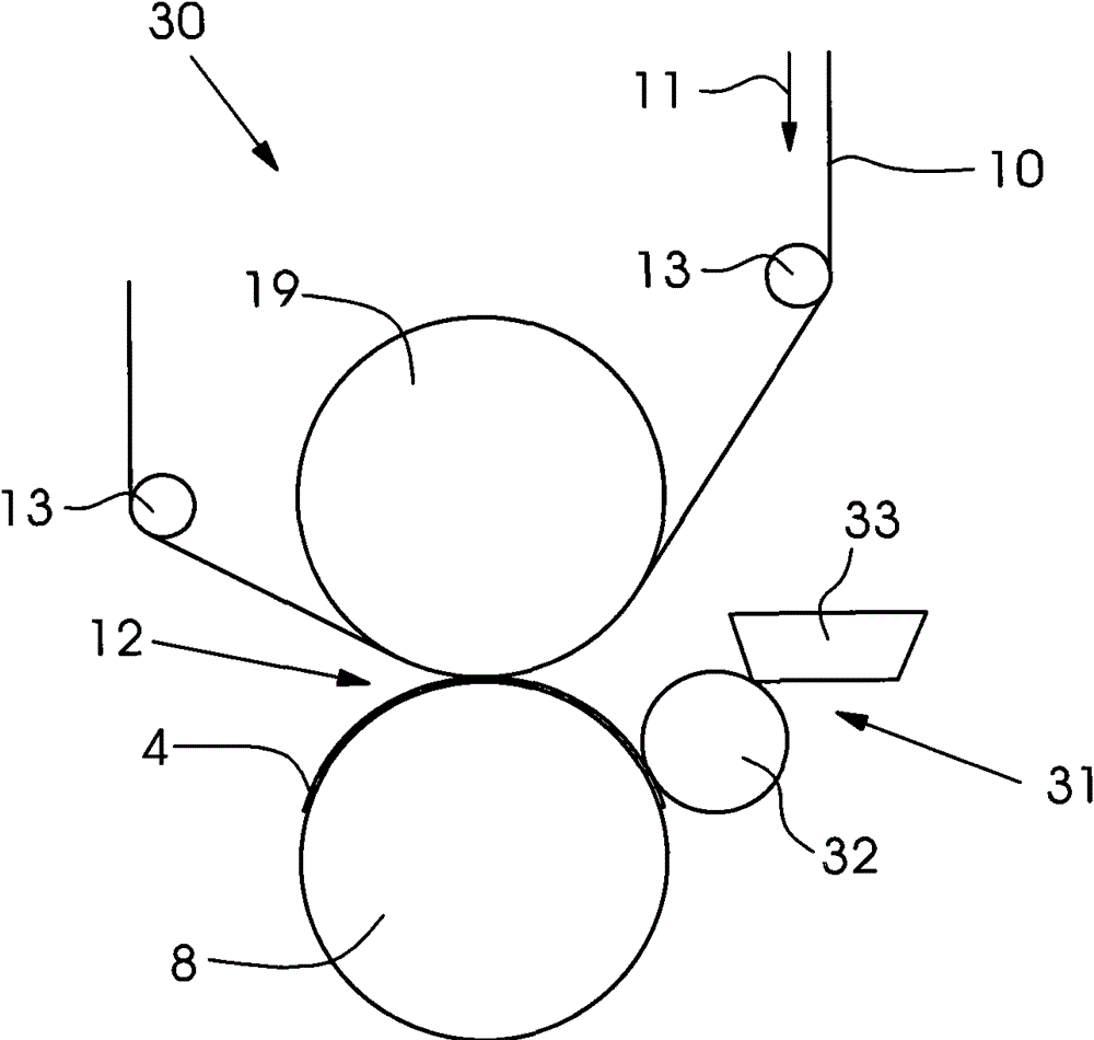
[0028] A sheet 4 is conveyed as a substrate through the laminating device 1 in direction 5 . During this conveyance, the sheet 4 first passes through the printing nip 6 , in which the adhesive is applied to the sheet 4 at least in the region where the laminating foil 41 is to be subsequently applied. The printing nip 6 is formed by an impression cylinder 8 and a blanket cylinder 7 , which serves here as an application cylinder. Via the forme cylinder and the inking unit pressed against it, the adhesive can be transferred via the application unit 2 to the sheet 4 instead of the ink regions, as in conventional inking units of printing presses. The sheet 4 loaded with adhesive in this way is conveyed via the transfer roller 9 into the laminating unit 3 and further passes through the laminating device 1 . In the lamination unit 3 the sheets 4 are guided through...


PUM


Abstract

The method involves supplying a substrate to a laminating plant. The laminating plant has a laminating cylinder (19) and an impression cylinder (8), which together forms a laminating gap (12). A laminating film (41) is applied on a carrier film (40), which together forms a composite film (10). The laminating film is transported together with the carrier film through a laminating gap. Independent claims are also included for the following: (1) a device for executing a substrate laminating method; and (2) a composite film with a separation or adhesion layer for use in a lamination process.

Description

technical field [0001] The invention relates to a method, a device and a composite foil for use in a corresponding method for laminating a substrate, wherein the substrate is supplied to a lamination unit comprising at least one layer Lamination rollers and counter rollers, which together form a lamination gap, to which lamination foil is supplied, said lamination foil passing through said lamination gap together with said substrate, wherein said lamination The foil is transferred under pressure onto the substrate in the lamination gap. Background technique [0002] When processing a substrate, preferably a printing material such as paper in sheet-fed or web form, it is often provided to increase the gloss of the printing material at least in regions or, for example, over the entire sheet or to protect the already printed printing material from further external influences. influences. [0003] In order to increase the gloss and / or to protect the printing material itself, i...

Claims


Application Information

Patent Timeline
Patent Type & Authority Patents(China)
IPC IPC(8): B32B37/10B32B37/12B32B38/04
CPCB41F19/008B32B37/1284B32B37/025B44C1/105B41F19/001B32B38/0004B41M7/0027
Inventor M·尤尔克维茨J·劳泰尔特J·松嫩沙因A·韦伯
Owner HEIDELBERGER DRUCKMASCHINEN AG
Why Eureka
Try Eureka