
Electric component installation structure for boat

A small technology for electrical components, applied in the direction of propulsion components, ship components, ships, etc., can solve problems affecting electrical components, etc., and achieve the effect of simplifying waterproof treatment

Inactive Publication Date: 2007-04-25
HONDA MOTOR CO LTD
View PDF6 Cites 0 Cited by
  • Summary
  • Abstract
  • Description
  • Claims
  • Application Information

AI Technical Summary

Problems solved by technology

[0007] Usually, for this kind of small boat, its instruction manual etc. instructs to lift the above-mentioned exhaust outlet (opening) 3a side (so that water does not intrude from the opening 3a) and turn it in the recovery direction of the overturned hull 1 to restore it, Therefore, in the case shown in FIG. 15(b), water is likely to affect the electrical component 4a disposed on the opposite side to the opening 3a (the left side in the direction of travel in FIG. 15(b)).

Method used


Image

  • Electric component installation structure for boat
  • Electric component installation structure for boat
  • Electric component installation structure for boat

Examples


Embodiment Construction

[0031] Embodiments of the present invention will be described below with reference to the drawings.

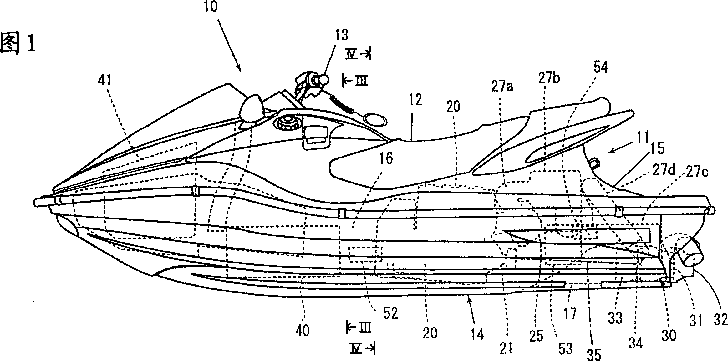
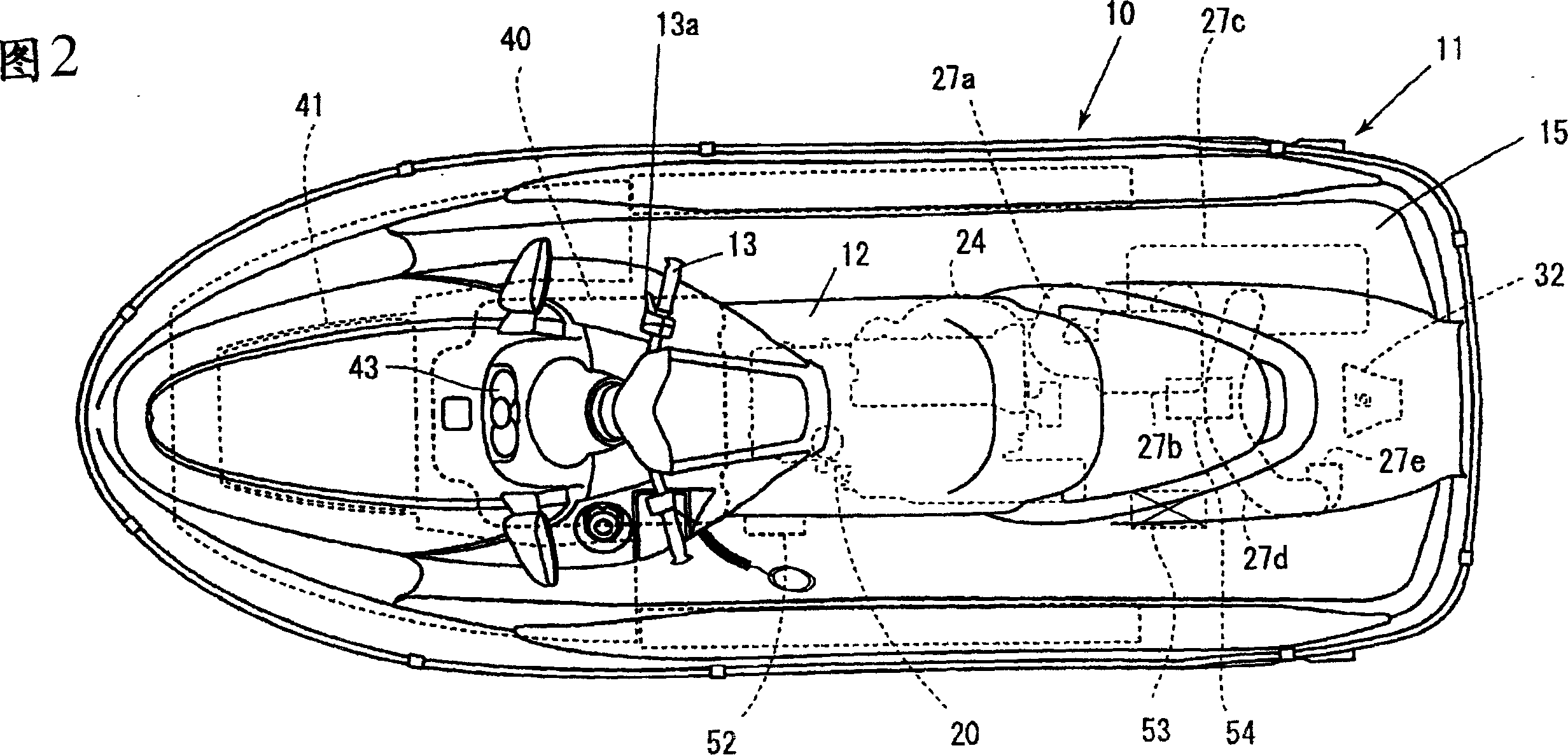
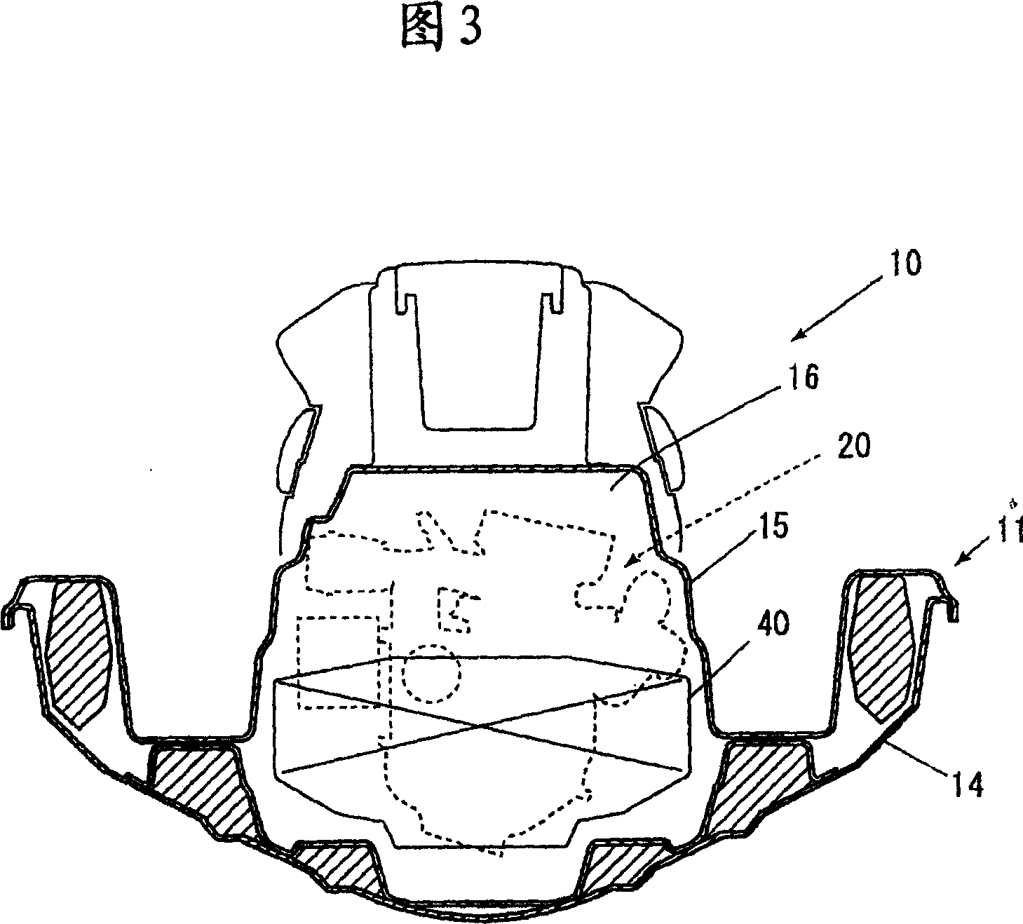
[0032] Fig. 1 is a schematic side view showing an example of a small planing boat using an embodiment of an electrical component installation structure of a small boat according to the present invention, Fig. 2 is a plan view thereof, and Fig. 3 is a partially enlarged section of III-III in Fig. 1 Figure (partially omitted cross-sectional view).

[0033] As shown in these figures (mainly Fig. 1), this small planing boat 10 is a saddle type small ship, and the occupant sits on the seat 12 of the hull 11, and can hold the steering handle 13 with the throttle control rocker to operate.

[0034] The hull 11 has a floating body structure in which a space 16 is formed inside by joining a hull 14 and a deck 15 . A water-cooled engine 20 is mounted on the hull 14 at a substantially central portion of the space 16 (a substantially central portion relative to front, rear, left, and rig...


PUM


Abstract

To provide an electrical component mounting structure for a personal watercraft, which is capable of suppressing electrical components from being splashed with water, thereby simplifying a waterproof treatment of the electrical components. A body 11 of a personal watercraft is composed of a hull 14 constituting a lower portion of the body 11 and a deck 15 for covering an upper portion of the hull 14, and an exhaust outlet 27e of the exhaust pipe 27d of an engine 20 disposed in the body 11 is formed on one side of the body 11 in the lateral direction. In this personal watercraft, electrical components 51 to 56 are disposed in the body 11 in such a manner as to be offset on the one side from a central portion in the lateral direction, and any electrical component is not disposed in the vicinity of a wall surface constituting the other side of the body 11. The electrical components are preferably disposed in the body 11 at an intermediate portion in the vertical direction, and at least one of a plurality of the electrical components is preferably mounted to a side wall constituting the one side of the body 11.

Description

technical field [0001] The present invention relates to a small boat (watercraft) electrical component installation structure. Background technique [0002] Conventionally, a structure as shown in FIG. 15 is known as an electrical component mounting structure of a small boat (Japanese Patent Application Laid-Open No. 10-194195). [0003] The hull 1 is composed of a hull 1a constituting its lower part and a deck 1b covering its upper part. The exhaust outlet 3a of the exhaust pipe 3 of the engine 2 arranged in the hull 1 is on one side in the left-right direction of the hull 1 (in the Figure (b) is the opening (3a) on the right side of the direction of travel. [0004] Batteries 4a and 4b which are one main electrical component are separately arranged on the left and right sides of the hull 1 as shown in FIG. [0005] Such small boats often capsize because they are used for racing. In addition, there is often a small amount of water accumulated in the boat. [0006] In th...

Claims


Application Information

Patent Timeline
Patent Type & Authority Patents(China)
IPC IPC(8): B63H21/32B63B45/00B63H11/08B63B35/73B63B43/00B63J99/00
CPCB63B43/00B63B35/731B63B34/10
Inventor 船寄裕辅屋代知彦长谷川徹
Owner HONDA MOTOR CO LTD
Learn More