Optical device and its producing method, and laminated optical device and its producing method
A manufacturing method and technology of optical devices, applied in the direction of optical elements, optical elements, optics, etc., can solve problems such as difficulty in implementation, difficulty, cracking, etc., and achieve the effects of no solvent cracking, less light loss, and lower heating temperature
- Summary
- Abstract
- Description
- Claims
- Application Information
AI Technical Summary
Problems solved by technology
Method used
Image

Examples
no. 1 Embodiment
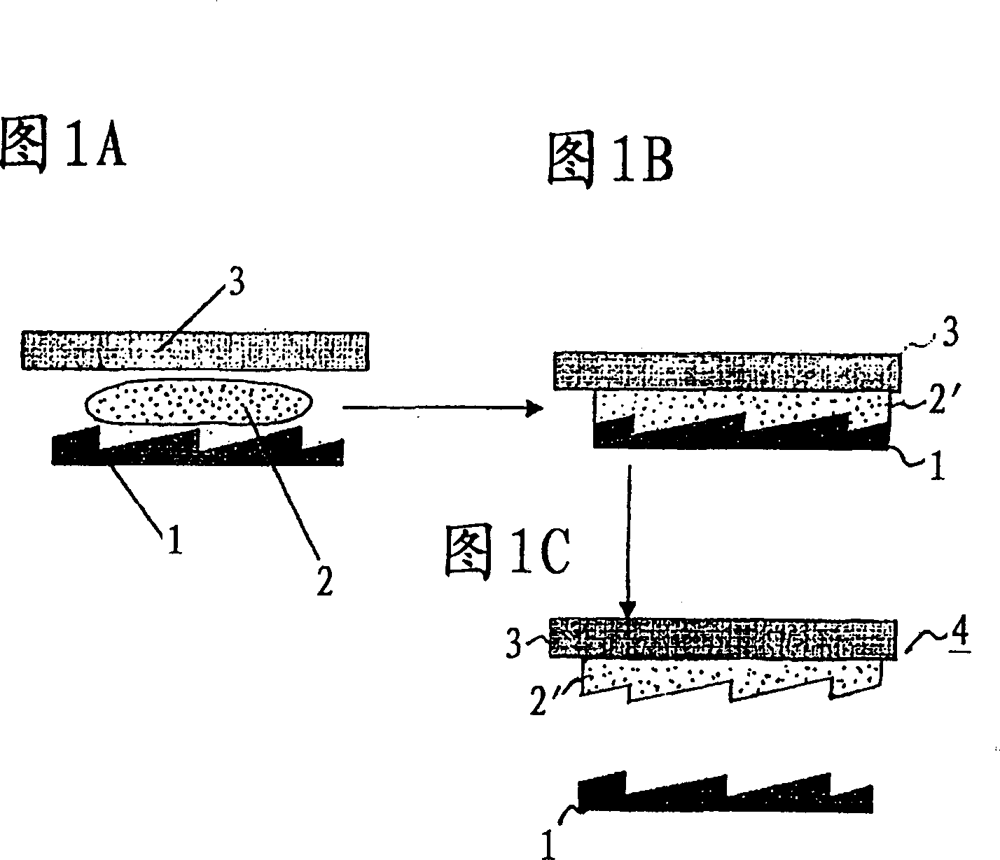
[0086] Referring to Figures 1A-1C, Figures 2A-2C, and image 3 , to describe the first embodiment of the present invention. First, as shown in FIG. 1A , a mold 1 processed into a diffraction grating shape was heated to 280° C. in a nitrogen atmosphere, and then a commercially available powder 2 of polyvinylcarbazole (manufactured by ACROS Corporation) was supplied. A glass (BK7) flat plate 3 is placed on it, and as shown in FIG. 1B , molding is carried out at 280° C. and a pressure of 20 MPa for 2 hours. Then, after gradually cooling to room temperature for 4 hours, as shown in FIG. 1C, the hardened polyvinylcarbazole 2' was released from the metal mold 1 to form a diffractive optical device 4.
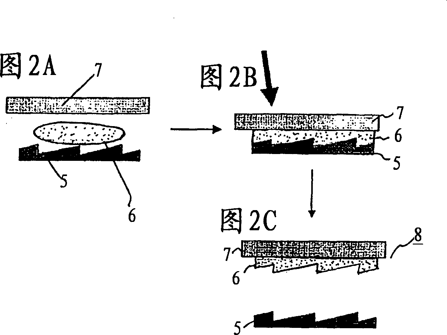
[0087] On the other hand, as shown in FIG. 2A, after heating the metal mold 5 processed into a diffraction grating shape to 280° C. in a nitrogen atmosphere, a photocurable resin 6 with optical characteristics (nd=1.513, vd=51.0) is flowed into the metal mold. Inside the mold 5. A ...
no. 2 Embodiment
[0097] A second embodiment of the present invention will be described with reference to FIGS. 8A to 8C. In this example, a solution 32 of 30 wt% polyvinylcarbazole (manufactured by ACROS) / chloroform was used instead of the powder 2 of polyvinylcarbazole (manufactured by ACROS) shown in the first example. In the second embodiment, the same reference numerals are assigned to the same components as those in the first embodiment, and description thereof will be omitted.
[0098]First, as shown in FIG. 8A, after heating the metal mold 31 in the shape of a diffraction grating to 280° C. in a nitrogen atmosphere, a solution 32 of 30 wt % polyvinylcarbazole (manufactured by ACROS) / chloroform was supplied. As shown in FIG. 8B , a glass (BK7) flat plate 33 was placed on it, and the solvent was dispersed at 70° C. for 24 hours. After vacuum drying at room temperature for 48 hours, as shown in FIG. 8C , the cured photocurable resin 32 ′ was released from the metal mold 31 to form a diffr...
no. 3 Embodiment
[0103] A third embodiment of the present invention will be described with reference to FIGS. 10A to 10C. In this example, N-vinylcarbazole 42 (manufactured by Tokyo Chemical Industry Co., Ltd.) was used as a fluid raw material for thermal polymerization instead of the powder of polyvinylcarbazole 2 shown in the first example. In the third embodiment, the same reference numerals are assigned to the same components as those in the first embodiment, and descriptions thereof are omitted.
[0104] First, as shown in FIG. 10A, after heating the metal mold 41 processed into the shape of a diffraction grating to 280° C. in a nitrogen atmosphere, N-vinylcarbazole 42 was supplied. As shown in FIG. 10B, a glass (BK7) plate 43 is placed on it, heated at 120° C. for 5 hours, and thermally polymerized and formed. By this heating, N-vinylcarbazole 42 is polymerized and converted into hardened polyvinylcarbazole 42'. Then, as shown in FIG. 10C , polyvinylcarbazole is released from the metal...
PUM
| Property | Measurement | Unit |
|---|---|---|
| transmittivity | aaaaa | aaaaa |
| Abbe number | aaaaa | aaaaa |
Abstract
Description
Claims
Application Information
 - R&D
- Intellectual Property
- Life Sciences
- Materials
- Tech Scout
- Unparalleled Data Quality
- Higher Quality Content
- 60% Fewer Hallucinations
Browse by: Latest US Patents, China's latest patents, Technical Efficacy Thesaurus, Application Domain, Technology Topic, Popular Technical Reports.
© 2025 PatSnap. All rights reserved.Legal|Privacy policy|Modern Slavery Act Transparency Statement|Sitemap|About US| Contact US: help@patsnap.com