
Waveform and frame structure for fixed wireless loop synchronous CDMA communications system

A communication system and synchronization field technology, applied in radio transmission system, multiplexing communication, time division multiplexing system, etc., can solve problems such as delay

Inactive Publication Date: 2001-01-24
L 3 COMM CORP
View PDF0 Cites 12 Cited by
  • Summary
  • Abstract
  • Description
  • Claims
  • Application Information

AI Technical Summary

Problems solved by technology

However, this approach introduces a delay in order to transmit all control messages for a particular frame in a block at the beginning or end of the frame

Method used


Image

  • Waveform and frame structure for fixed wireless loop synchronous CDMA communications system
  • Waveform and frame structure for fixed wireless loop synchronous CDMA communications system
  • Waveform and frame structure for fixed wireless loop synchronous CDMA communications system

Examples


Embodiment Construction

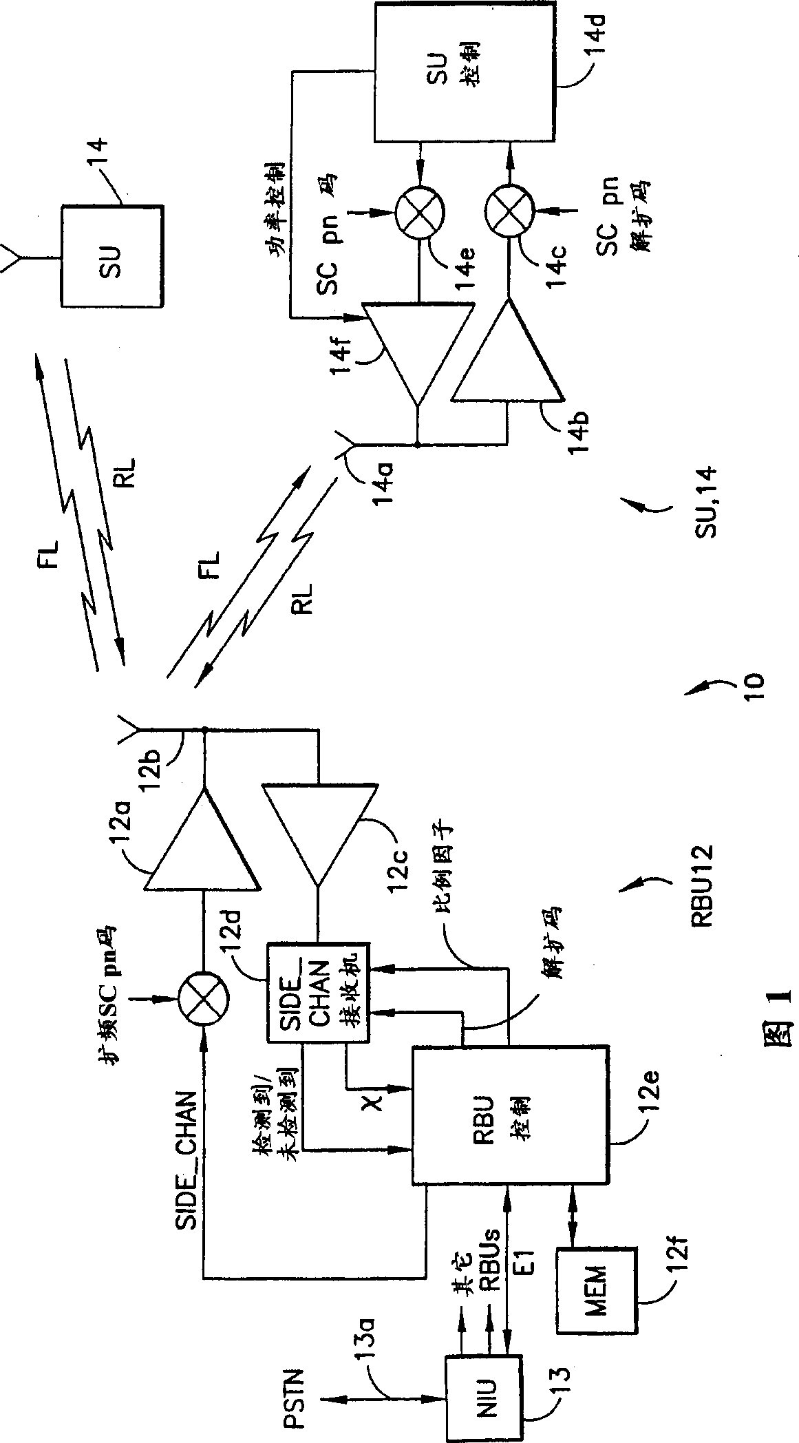
[0028] By way of introduction, and with reference to FIG. 1, it can be seen that a fixed wireless system (FWS) 10 in a preferred embodiment of the present invention is a custom system based on digital radio technology. Specifically, the FWS 10 uses the CDMA technology based on direct sequence spread spectrum through the air link to provide users with local access. It's high quality, reliable, and competitive with wired options at a cost. FWS 10 has high spectral efficiency, so it can provide services of good wired quality with limited bandwidth. The large dynamic range of the FWS 10 enables it to be used in pico, micro or mini (mini) cellular architectures, meeting the needs of densely populated metropolitan, urban and suburban groups while being very economical.

[0029] Some of the key features of FWS 10 include: wired voice quality at 32 kbps; data and fax throughput at 32 kbps; high service reliability and good immunity to interference; secure air link; and support for E...


PUM


Abstract

Disclosed is a method for transmitting information in a CDMA communication system, the method including steps of (a) multiplexing data and control information into a data stream; (b) encoding the data stream to form a stream of encoded I / Q symbol pairs; (c) inserting synchronization information into the stream of encoded I / Q symbol pairs; and (d) spreading the encoded I / Q symbol pairs and the inserted synchronization information using a same pseudonoise (pn) spreading code prior to transmission as a frame. The preferred frame structure includes an unencoded synchronization field followed by a plurality of multi-byte data fields. Individual ones of the plurality of data fields are separated by a control message field. Individual ones of the control message fields contain a single byte of a multi-byte control message frame.

Description

field of invention [0001] The present invention relates generally to wireless local loop systems and, in particular, to fixed wireless loop systems providing voice and data communications between a radio base unit and a plurality of subscriber stations. Background of the invention [0002] The traditional definition of a local loop is that part of the network that connects a customer's home to a central office switch. However, this is an extended definition, which is not the case when the network is extended to the local ring via digital loop carriers and digital cross-connects. In the present invention, the local ring refers to the connection from the user's residence to the network connection point, no matter how this connection is realized. [0003] Until recently, the local ring used mainly copper wires, supplemented by microwave radio links for remote areas or rough terrain. In the last decade, fiber has entered the local ring (also known as the "access" network), bri...

Claims


Application Information

Patent Timeline
IPC IPC(8): G06F11/10H04BH04B1/707H04B7/216H04B7/26H04L1/00H04B15/00H04J3/00H04J3/24H04K1/00H04L1/02H04L7/00
CPCH04B1/707H04B1/7085
Inventor P·L·斯蒂芬森T·R·吉尔洛伦兹J·M·哈里斯L·A·布特菲尔德M·J·胡尔斯特D·格里芬R·汤普森
Owner L 3 COMM CORP
Learn More