
Heat lamination of dry photoresist film onto board for printed circuit

A circuit board, thermal lamination technology, applied in printed circuits, use/removal methods of circuit masks, printed circuit manufacturing, etc., can solve problems such as slow running process

Inactive Publication Date: 2006-07-19
阿梅代奥·坎多雷
View PDF1 Cites 0 Cited by
  • Summary
  • Abstract
  • Description
  • Claims
  • Application Information

AI Technical Summary

Problems solved by technology

With this system, the sticking operation is no longer a critical step, since the tape no longer has to be pulled by the advancing board, yet the overall running process is slowed down

Method used


Image

  • Heat lamination of dry photoresist film onto board for printed circuit
  • Heat lamination of dry photoresist film onto board for printed circuit
  • Heat lamination of dry photoresist film onto board for printed circuit

Examples


Embodiment Construction

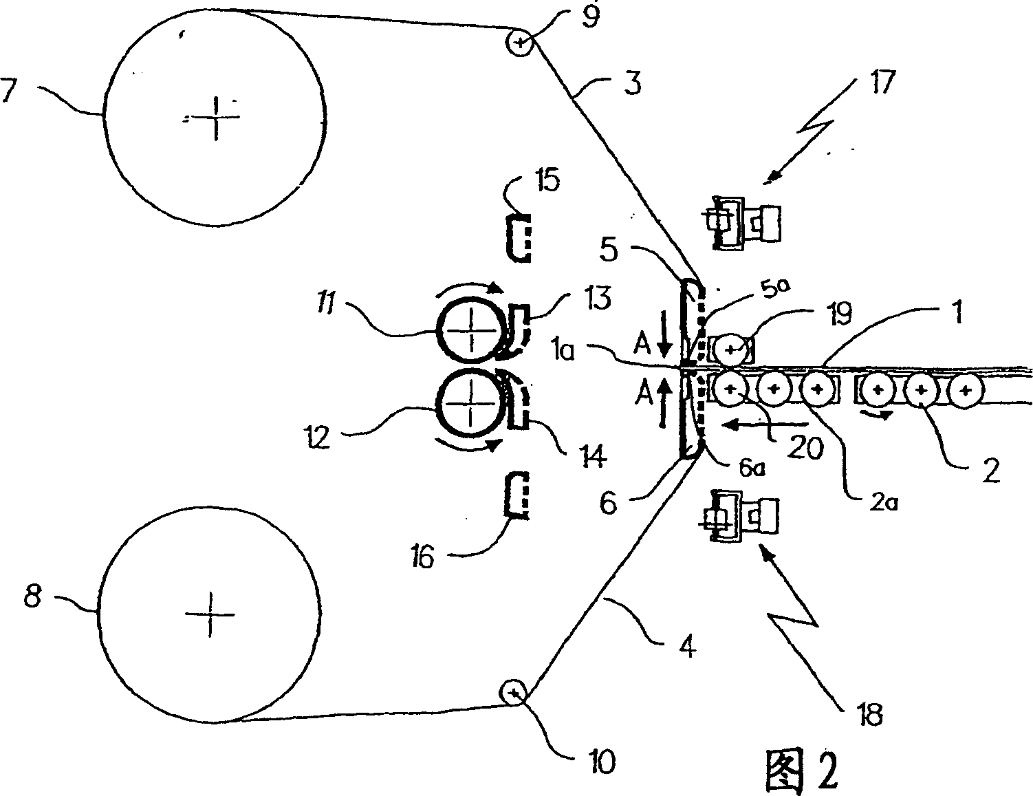
[0027] The various stages of the entire stroke (or cycle) of the automatic laminator of the present invention are schematically represented in the appended figure 1 to 7.

[0028] In the described examples, it is assumed that a dry photoresist film is placed on both surfaces of the printed circuit board, as this is the most common case. The machine of the invention is of course also suitable for placing dry photoresist film onto only one surface of the circuit board by simply stopping the lamination of the relevant mechanism relative to the dry photoresist film on the other side of the circuit board.

[0029] figure 1 Represents the main components of an automatic laminator of the present invention that is idle or waiting for the arrival of new circuit boards 1, where the circuit boards are usually preheated to a certain temperature.

[0030] The circuit board 1 is finally moved towards the lamination section of the laminator by means of a conveyor 2 .

[0031] During the p...


PUM

PropertyMeasurementUnit
Hardnessaaaaaaaaaa

Abstract

An automatic machine for hot laminating a dry photoresist film supported on a peelable-off cover sheet onto a board for printed circuit, includes at least a pair of hot laminating rolls, transfer means for feeding a preheated board to the inlet side of said pair of laminating rolls, at least a supply roll of a rolled-up continuous ribbon of said supported dry photoresist film, vacuum means holding a free end portion of the supported dry photoresist film ribbon, means for pressing and tacking the leading edge of said vacuum held free end portion of the ribbon at a given position on a surface of a board moving towards the inloet side of said pair of laminating rolls, cutting means associated to said ribbon end holding and tacking means for cutting to measure, on account of the length of the fed board, the dry photoresist film ribbon carried along by the moving board onto which the leading edge of the ribbon has been tacked by said tacking means.

Description

technical field [0001] This invention relates to the manufacturing process of printed circuit boards, and more particularly to techniques and machines for laminating a dry photoresist film to printed circuit boards. Background technique [0002] One of the early steps in the manufacture of printed circuits is the placement of a photoresist film on one or both sides of a copper laminate circuit board for printed circuits, whereby a UV source is passed through the corresponding area of ​​the circuit to be implemented. A photographic mask that exposes and polymerizes a photoresist film. [0003] The photoresist film layer can be applied in liquid form, or usually placed as a dry photoresist film, which is carried on a cover layer, which can be easily peeled off for the application of The photoresist film is exposed. [0004] To apply the photoresist film to the surface of one or both sides of the circuit board, special thermal lamination machines are used, which usually consi...

Claims


Application Information

Patent Timeline
IPC IPC(8): B32B37/00B32B37/06G03F7/16G03F7/20H05K3/00B32B7/06B32B15/08B32B37/22H05K3/06
CPCB32B37/226B32B37/0007B32B37/0053B32B2457/08H05K3/0079H05K3/00
Inventor 阿梅代奥·坎多雷
Owner 阿梅代奥·坎多雷
Learn More