
Method for mfg. overcurrent protection component

A technology for protecting components and manufacturing methods, which is applied in the direction of resistance manufacturing, electrical components, and current-responsive resistors, etc., to achieve the effects of reducing heating, reducing deformation and stress, and increasing sensitivity

Inactive Publication Date: 2006-04-26
POLYTRONICS TECH
View PDF1 Cites 0 Cited by
  • Summary
  • Abstract
  • Description
  • Claims
  • Application Information

AI Technical Summary

Problems solved by technology

[0008] The purpose of the present invention is to provide a method for manufacturing an overcurrent protection element that can improve the stability and sensitivity of the overcurrent protection element, and can prevent defects such as deformation or increased internal stress caused by local heating caused by punching

Method used


Image

  • Method for mfg. overcurrent protection component
  • Method for mfg. overcurrent protection component
  • Method for mfg. overcurrent protection component

Examples


Embodiment Construction

[0025] Structural features of the present invention are described in detail as follows in conjunction with accompanying drawing and embodiment:

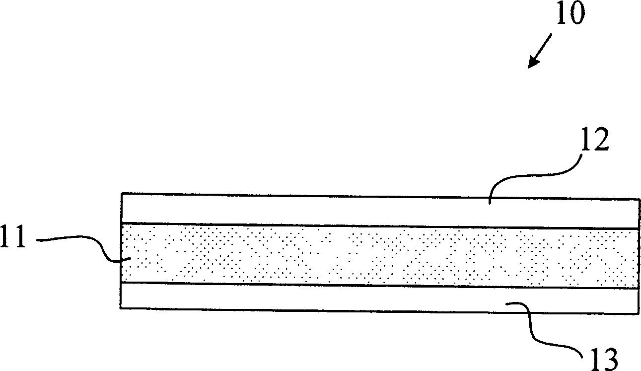
[0026] like figure 1 As shown, the overcurrent protection element 10 includes: a current sensing element 11 , an upper electrode foil 12 and a lower electrode foil 13 . The current sensing element 11 is made of conductive composite material with positive temperature coefficient (PTC), including at least polymer and conductive filler. The upper electrode foil 12 and the lower electrode foil 13 are pasted on two sides of the current sensing element 11 .

[0027] The polymer used to prepare the PTC conductive composite material includes at least one crystalline or non-crystalline polymer, such as polyethylene, polypropylene, polyoctene and mixtures thereof.

[0028] The conductive filler is dispersed in the polymer and is selected from the group consisting of carbon black, metal particles, graphite, ceramic powder and mixtures thereof...


PUM


Abstract

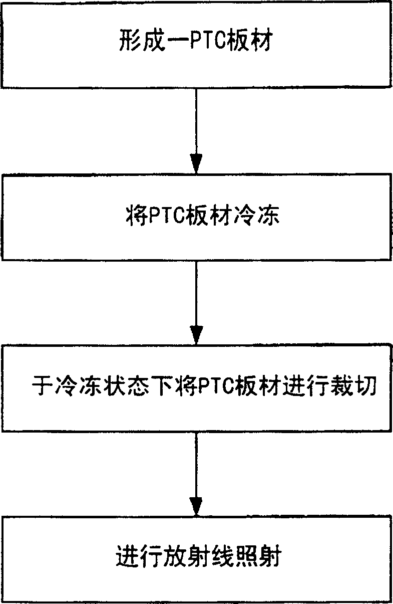
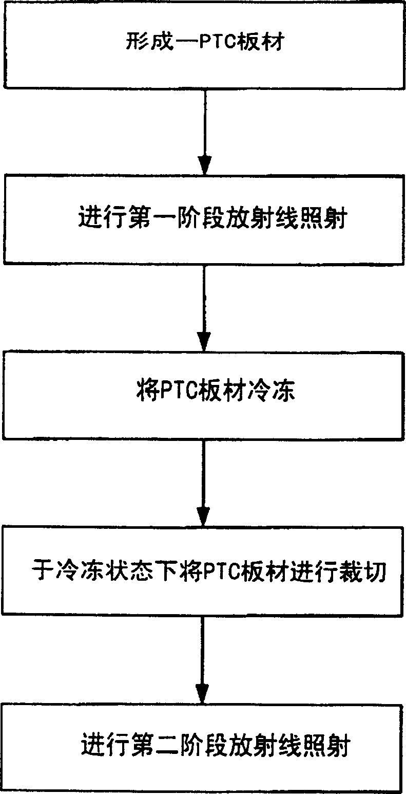
A method for manufacturing an overcurrent protection element, comprising the steps of: a. providing a plate with a positive temperature coefficient, the plate comprising: a plate formed of a conductive composite material with a positive temperature coefficient and two electrodes bonded to its two surfaces Foil; b. freezing the plate with positive temperature coefficient to a low temperature state; c. punching the plate into several overcurrent protection elements in a low temperature state; d. irradiating the formed overcurrent protection element with radiation; it may also include The steps are as follows: before step b, the plate with positive temperature coefficient is irradiated with radiation in the first stage, so that the conductive composite material undergoes a preliminary cross-chain reaction; step d is the second stage of radiation irradiation. The method of the invention can increase the sensitivity of the overcurrent protection element to temperature, and its electrical performance is more stable.

Description

(1) Technical field [0001] The invention relates to an overcurrent protection element, especially a manufacturing method of the overcurrent protection element. (2) Background technology [0002] like figure 1 As shown, the existing overcurrent protection element 10 includes: a current sensing element 11, an upper electrode foil 12 and a lower electrode foil 13; since the resistance value of the current sensing element 11 is sensitive to temperature changes, It has been widely used to protect batteries or circuit components. [0003] Currently, the more common current sensing element 11 is made of a conductive material with a positive temperature coefficient (Positive Temperature Coefficient: PTC), which includes polymers and conductive fillers. The resistance value of PTC conductive composite materials is sensitive to temperature changes. Under normal use conditions, its resistance can maintain a very low value, so that the circuit can operate normally. However, when over ...

Claims


Application Information

Patent Timeline
Patent Type & Authority Patents(China)
IPC IPC(8): H01C7/13H01C7/02H01C17/00
Inventor 朱复华王绍裘游志明
Owner POLYTRONICS TECH
Learn More