Passive full optical-fiber adjustable optical tapping element

A splitter and all-fiber technology, which is applied in the field of passive all-fiber adjustable optical splitters, can solve the problems of practical device reports without passive adjustable optical splitters, and achieve simple structure and low insertion loss , easy to achieve effect

Inactive Publication Date: 2006-04-05
SHANGHAI JIAOTONG UNIV
View PDF1 Cites 1 Cited by
  • Summary
  • Abstract
  • Description
  • Claims
  • Application Information

AI Technical Summary

Problems solved by technology

[0008] After these investigations, although the research on FBT-based dimmable splitters has also been reported, a lot of work still needs to be done in terms of practicality. So far, there is no passive dimmable splitter based on this principle. Practical devices are reported

Method used


Image

  • Passive full optical-fiber adjustable optical tapping element
  • Passive full optical-fiber adjustable optical tapping element
  • Passive full optical-fiber adjustable optical tapping element

Examples


Embodiment Construction

[0023] The technical solutions of the present invention will be further described below in conjunction with the accompanying drawings and embodiments.

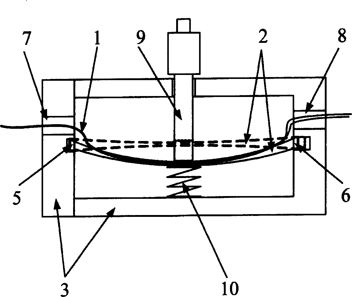
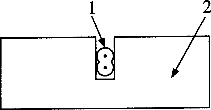
[0024] figure 1 Shown is a schematic structural diagram of an embodiment of a 1×2 passive adjustable optical splitter of the present invention. Such as figure 1As shown, the fused tapered optical fiber 1 is fixedly embedded on the elastic sheet 2, and its coupling region is located near the center of the elastic sheet 2. The two ends of the elastic sheet 2 are respectively embedded in the two grooves at the two ends of the shell 3, wherein the fixing groove 5 is closely matched with one end of the elastic sheet 2, the elastic sheet cannot slide in the groove, and the sliding groove 6 is loosely fitted with the other end of the elastic sheet 2, The end of the elastic sheet in the groove can slide freely in the groove. An optical fiber lead-out hole 7 and 8 are respectively arranged at both ends of the housing. In the vertic...


PUM


Abstract

This invention relates to a passive complete light fiber adjustable light splitter, which comprises a melting conical fiber and one fine adjusting apparatus to adjust optical fiber curvature. The melting conical fiber is fixed and imbedded on the elastic pad of the adjust apparatus and the two ends of the elastic pad are separately imbedded in the fixed trough and sliding trough. The thin fringe screw bar is directly pressed on the middle of the elastic pad. The relative other side of the elastic pad is located with a spring tightly on the elastic pad. The thin fringe screw bar adjusts the curvature of the elastic pad to change the curvature of the couple area of melting conical fiber and to realizes the distribution ratio adjusting of the light power on each output ends. This invention can be applied in each light transition network as light splitter, adjustable attenuator.

Description

technical field [0001] The invention relates to a passive all-fiber adjustable optical splitter, which is suitable for optical fiber communication systems and networks. Background technique [0002] Optical splitter is one of the most widely used optical components in optical transmission system. An optical splitter is sometimes called an optical beam splitter or an optical power splitter. It is a commonly used device that divides the light input into the optical fiber port into multiple parts according to a certain ratio and outputs it from multiple output optical fiber ports. As a splitting device of optical signals, optical splitters are widely used in optical communication systems and networks, such as optical broadcasting, multicasting, protection, and optical signal monitoring. Conventional optical splitters are usually implemented using Fused Biconical Taper-FBT technology. The power distribution ratio of each output port of the formed splitter is fixed and cannot be...

Claims


Application Information

Patent Timeline
Patent Type & Authority Patents(China)
IPC IPC(8): G02B6/24G02B6/255H04B10/12
Inventor 胡佩钢胡卫生肖石林何浩
Owner SHANGHAI JIAOTONG UNIV
Why Eureka
Try Eureka