Air lift separator

A separator and air stripping technology, applied in the field of final product separation and air stripping process, can solve the problems of complex and unsafe operation process, easy occurrence of bias flow, channel flow, easy occurrence of gas phase entrainment, etc., to achieve simple and safe operation, easy liquid Bit detection, the effect of enhanced sensitivity

Inactive Publication Date: 2006-02-22
CHINA PETROLEUM & CHEM CORP +1
View PDF1 Cites 0 Cited by
  • Summary
  • Abstract
  • Description
  • Claims
  • Application Information

AI Technical Summary

Problems solved by technology

The second method is to add alkaline water to wash in the oil. The disadvantage of this method is that it cannot be operated continuously, and at the same time it will reduce the liquid collection and corrode the equipment. The operation process is complicated and unsafe, and the oil is in contact with air, which is easy Oxidation, causing errors in test results
The third method is a semi-automatic air lift method, which is mainly to add a closed container at the rear of the low-pressure separator, and feed the air lift gas to purge the oil in the container, but it is easy to cause liquid entrainment, and the air lift effect is not ideal. A closed container needs to be added behind the low-pressure separator
[0004] The flow rate of the liquid phase in the small or medium-sized test device in the laboratory is small. If it is subjected to continuous gas stripping treatment, bias flow and channel flow will easily occur, the gas-liquid contact efficiency will be low, the gas lift effect will be poor, and gas phase entrainment will easily occur. continuous oil discharge

Method used


Image

  • Air lift separator
  • Air lift separator
  • Air lift separator

Examples


Embodiment Construction

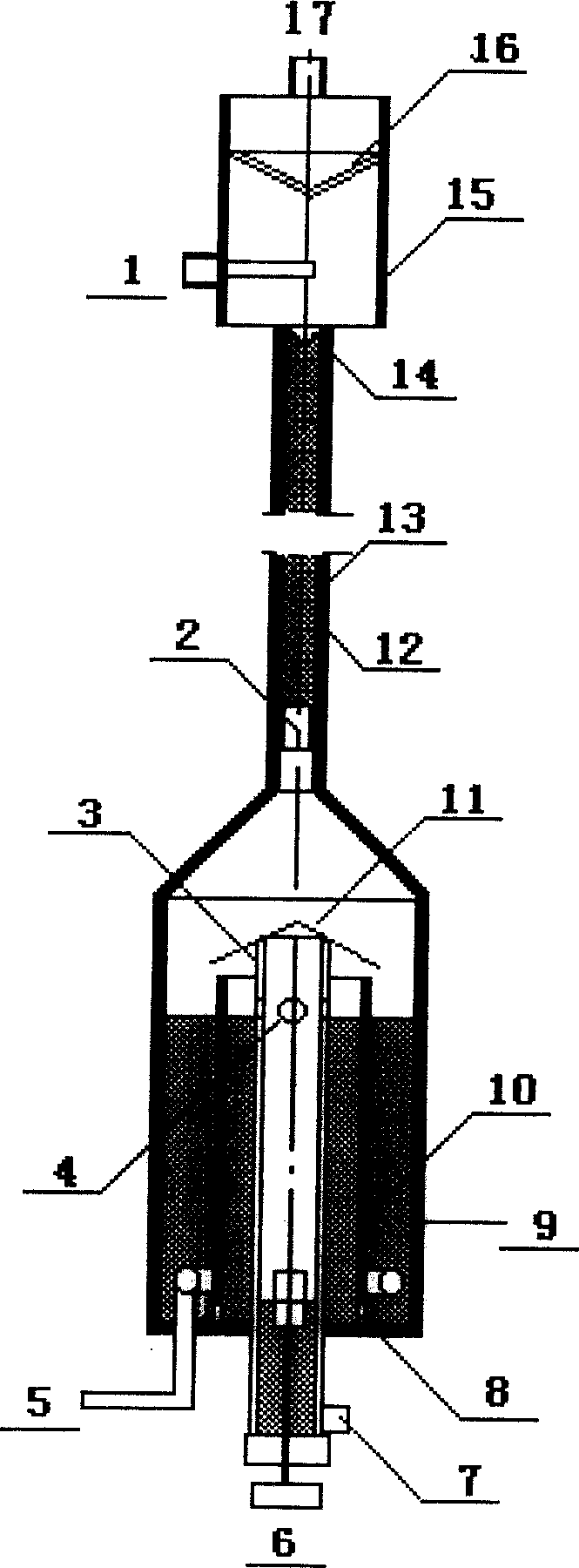
[0011] The structure and operation method of the air stripping separator of the present invention will be further described below in conjunction with the accompanying drawings.

[0012] Such as figure 1 As shown, the structural composition and working process of the oil discharge mechanism at the bottom of the air lift separator of the present invention are as follows: the oil discharge pipe 3 and the diversion sleeve 10 are respectively placed in the liquid collector 9 from the inside to the outside, and the upper part of the oil discharge pipe 3 is installed with a flow guide Cover 11, the lower part of the diversion sleeve 10 is provided with a number of bottom holes 8, the upper part of the oil discharge pipe 3 is provided with a plurality of diversion holes 4, the lower part is provided with an oil outlet 7 and a liquid level detector 6 is installed. 9 and the lower part between the guide sleeve 10 is arranged an annular blowing pipe 5 .

[0013] When the liquid flowing ...


PUM


Abstract

The present invention discloses a continuous type gas stripping separator. It comprises bottom oil discharge mechanism (flow guide sleeve, liquor collector, flow guide cover, oil discharge pipe, flow guide hole and gas-blowing pipe) and gas stripping separation mechanism (gas-liquid contact pipe, gas stripping pipe, filler, fiquid liquid distributor and foam-breaking net). As compared with existent technology said invention has the following advantages: 1. gas-liquid separation process and gas tripping process can be simultaneously implemented in a fully-closed container, it can prevent liquid phase from contacting with air; 2 gas-liquid contact is full, gas stripping effect is good and oil quality can be raised; and 3 its operation is safe, working efficiency is raised and lobour intensity can be reduced.

Description

technical field [0001] The invention belongs to an air-lifting separator, and is especially suitable for terminal product separation and air-lifting process in a laboratory small device or a medium-sized experimental device. Background technique [0002] Air stripping is a common method for separating a small amount of volatile substances in the liquid phase. It is widely used in industry, mainly in the form of plate tower, packed tower and empty tower. For example, CN1102355A discloses a gas stripping removal device for volatile matter in a liquid. The liquid is mixed with the stripping gas by an injector, and then enters a separation container for gas-liquid separation. The separation container is an empty cylinder structure. [0003] However, in the laboratory small or medium-sized experimental devices that simulate the working conditions of industrial devices, due to the small flow rate of the processed materials, conventional air lift devices cannot operate normally, an...

Claims


Application Information

Patent Timeline
Patent Type & Authority Patents(China)
IPC IPC(8): B01D3/00
Inventor 张志华吴宜冬于丹
Owner CHINA PETROLEUM & CHEM CORP
Why Eureka
Try Eureka