Electronic emission device, electron source and image forming apparatus using the same device and its producing method
A technology of electron emission and electron source, applied in the field of electron source, can solve the problems of unsatisfactory electron emission characteristics and efficiency
Inactive Publication Date: 2005-10-12
CANON KK
View PDF0 Cites 0 Cited by
- Summary
- Abstract
- Description
- Claims
- Application Information
AI Technical Summary
Problems solved by technology
[0010] However, the above-mentioned electron-emitting device proposed by M. Hartwell is not satisfactory in terms of stable electron-emitting characteristics and efficiency
Method used
View moreImage
Smart ImageViewing Examples
Examples
 PUM
| Property | Measurement | Unit |
|---|---|---|
| Particle size | aaaaa | aaaaa |
| Resistance | aaaaa | aaaaa |
| Thickness | aaaaa | aaaaa |
Abstract
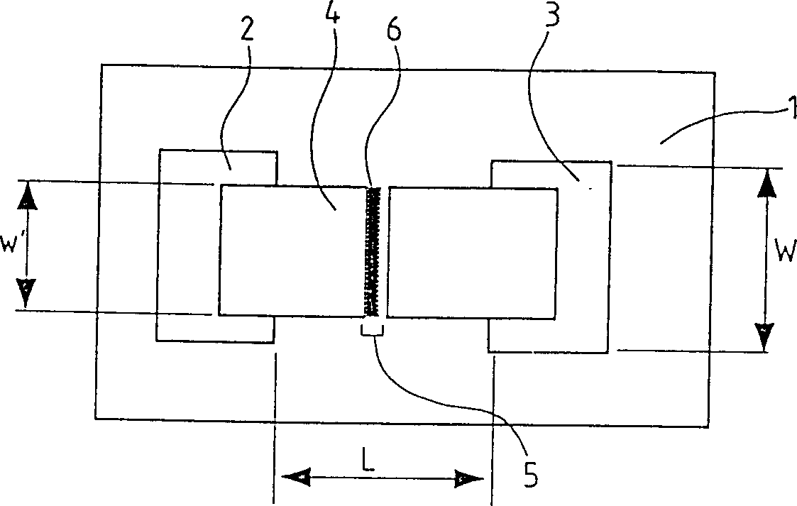
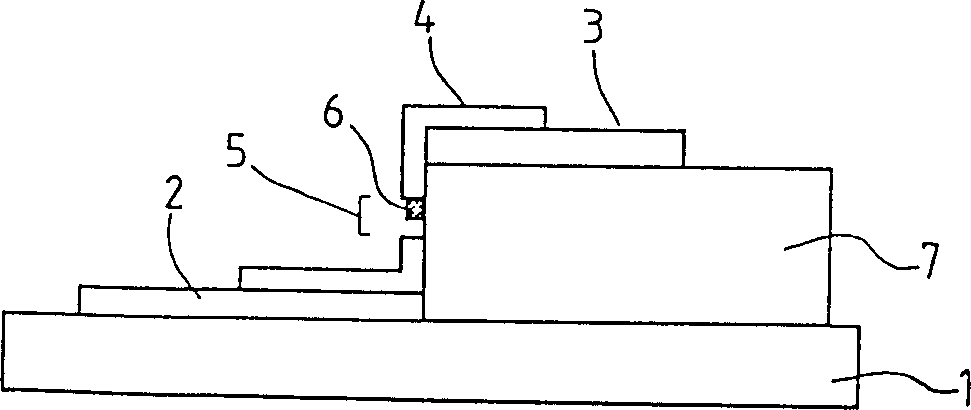
In an electron-emitting device including, between electrodes, an electroconductive film having an electron emitting region, the electroconductive film has a film formed in the electron emitting region and made primarily of a material having the higher melting point than that of a material of the electroconductive film. Alternatively, the electroconductive film has a film formed in the electron emitting region and made primarily of a material having a higher temperature, at which the material develops a vapor pressure of 1.3 x 10<-><3> Pa, than that of a material of the electroconductive film. A manufacture method of an electron-emitting device includes a step of forming a film made primarily of a metal in the electron emitting region of the electroconductive film. An image-forming apparatus comprising the electron-emitting devices has high luminance and excellent stability in operation.
Description
technical field [0001] The present invention relates to an electron-emitting device, and more particularly to an electron-emitting device that maintains stability over a long period of time, an electron source using the electron-emitting device, an image forming apparatus such as a display device using the electron source, and an exposure device. device, and a method of manufacturing an electron-emitting device, an electron source, and an image forming device. Background technique [0002] There have been two main types of electron-emitting devices in the past, namely, a hot cathode type electron-emitting device and a cold cathode type electron-emitting device. The cold cathode type electron emission devices include field emission type (hereinafter abbreviated as FE), metal / insulator / metal layer type (hereinafter abbreviated as MIM) and surface conduction type. [0003] Examples of FE electron-emitting devices are in W.P. Dyke and W.W. Dolan, "Field emission" ("Field emissi...
Claims
Login to View More Application Information
Patent Timeline
 IPC IPC(8): H01J9/02H01J1/316H01J29/04H01J29/46H01J31/12
CPCH01J2329/00H01J1/316H01J9/027H01J31/12
Inventor 岩崎达哉山野边正人塚本健夫山本敬介浜元康弘
Owner CANON KK
- R&D Engineer
- R&D Manager
- IP Professional
- Industry Leading Data Capabilities
- Powerful AI technology
- Patent DNA Extraction
Learn More Browse by: Latest US Patents, China's latest patents, Technical Efficacy Thesaurus, Application Domain, Technology Topic, Popular Technical Reports.
© 2024 PatSnap. All rights reserved.Legal|Privacy policy|Modern Slavery Act Transparency Statement|Sitemap|About US| Contact US: help@patsnap.com


