Optical attenuator module with automatic regulation function

An automatic adjustment and attenuator technology, applied in optics, nonlinear optics, instruments, etc., can solve the problems of difficult optical signal power level, stable consistency, poor stability, etc.

Inactive Publication Date: 2005-01-26
INST OF SEMICONDUCTORS - CHINESE ACAD OF SCI
View PDF0 Cites 0 Cited by
  • Summary
  • Abstract
  • Description
  • Claims
  • Application Information

AI Technical Summary

Problems solved by technology

[0004] 1 As far as the current technical level of lasers is concerned, it is still difficult to achieve stable and consistent power levels of optical signals of different wavelengths from different lasers
[0005] 2 Since the absorption coefficient of optical waveguide materials and optical fiber materials is related to wavelength, the power loss of optical signals of different wavelengths transmitted in optical devices and optical fibers is different
[0006] 3. Since the gain flatness of erbium-doped fiber amplifiers has not been well resolved, the gains obtained by optical signals of different channels passing through erbium-doped fiber amplifiers are also different.
[0007] 4 If an interference filter is used as a demultiplexer, the optical power loss of each channel is also different due to the different reflection times experienced by optical signals of different wavelengths
Currently commercialized optical attenuators include displacement optical attenuators, attenuating sheet optical attenuators, coating optical attenuators, and liquid crystal optical attenuators. The biggest problem with these types of optical attenuators is their large size. The device production process adopted is not compatible with the existing semiconductor process, so it cannot be integrated with other optoelectronic devices, and cannot achieve continuous online attenuation of optical signals, or the stability is not good (for example, the environmental performance of liquid crystal optical attenuators is extremely high. Poor), which cannot meet the requirements of modern communication systems for device miniaturization, integration and high environmental stability

Method used


Image

  • Optical attenuator module with automatic regulation function
  • Optical attenuator module with automatic regulation function
  • Optical attenuator module with automatic regulation function

Examples


Embodiment Construction

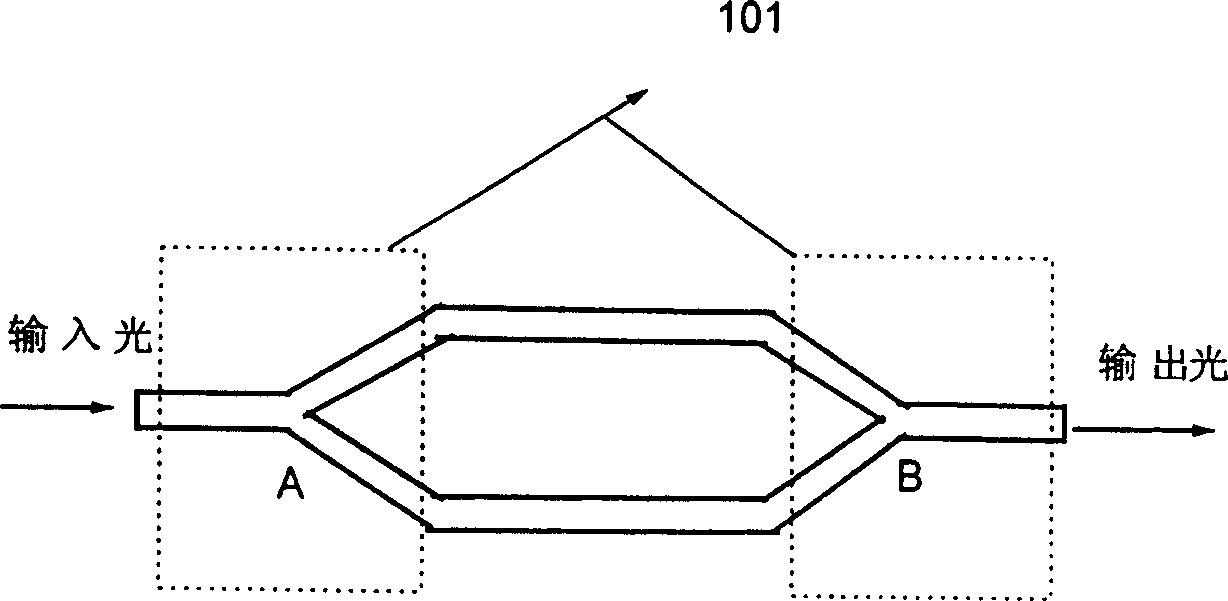
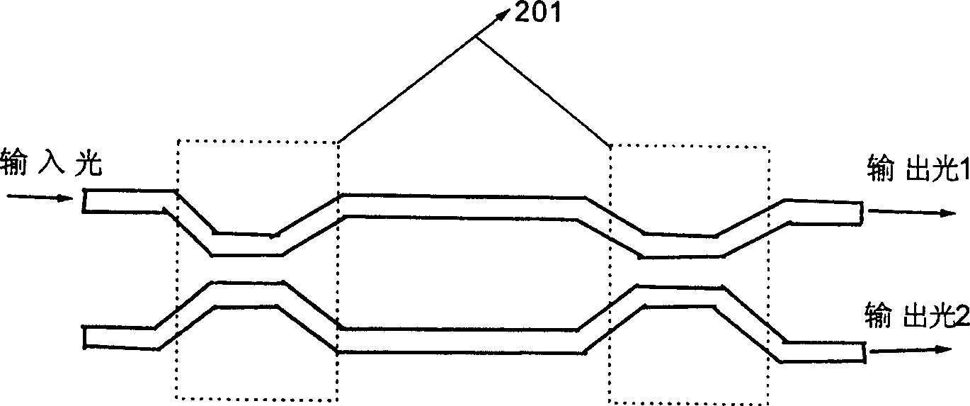
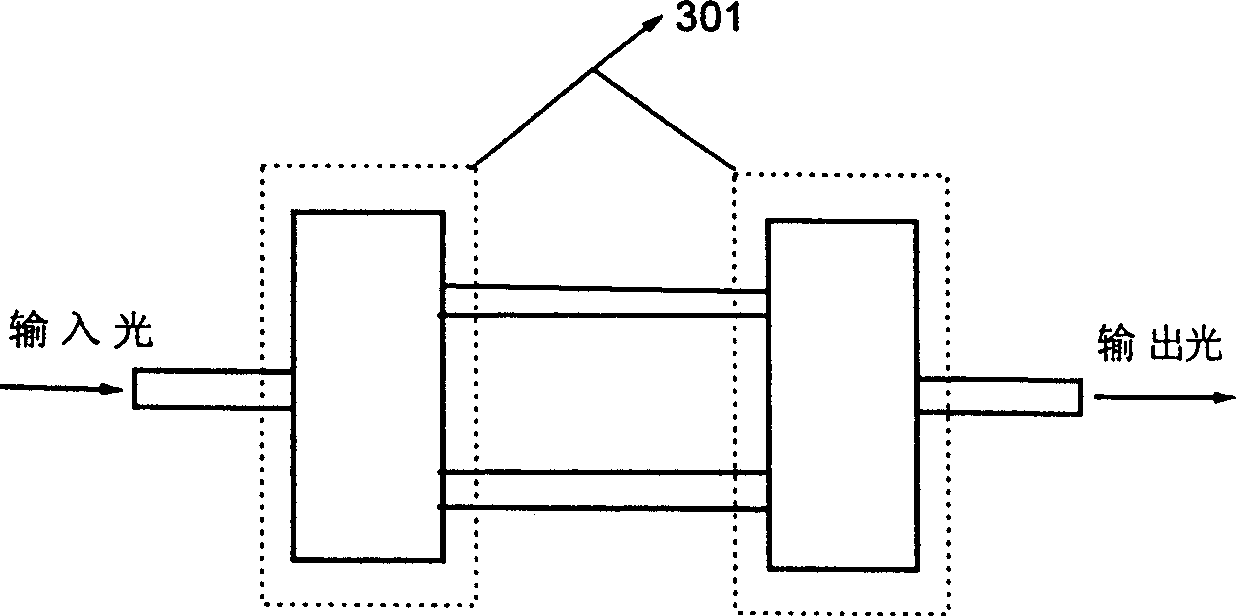
[0029] There are three main structures used to realize the optical attenuator: Y-branch optical attenuator (such as figure 1 shown), direct coupler optical attenuators (such as figure 2 shown), multimode interference optical attenuator (such as image 3 shown). No matter what kind of structure is adopted, its basic principle is the principle of Mache-Zender interferometer, which will be introduced first below.

[0030] The Gaussian beam coming out of the single-mode fiber is coupled into the device through the input waveguide. At node A, it is divided into two beams with equal intensity and enters two symmetrical single-mode waveguides respectively. Since the structures on both sides are symmetrical, the intensity of the two beams is equal, and the phase Also the same, the "Y"-shaped branch structure near the node A (referred to as the Y branch structure 101) mainly completes the function of dividing a beam of light into two beams in equal proportions, and the electric fiel...


PUM

PropertyMeasurementUnit
refractive indexaaaaaaaaaa

Abstract

The optical attenuator module with automatic regulation function includes input optical fibre array, optical attenuator array, output optical fibre array, photoelectric detector array, control circuit and driven circuit, in which between the input optical fibre array, optical attenuator array and output optical fibre array a high-efficiency alignment coupling is implemented, the photoelectric detector array is placed on the top of optical attenuator array and output optical fibre array, and a high-efficiency alignment coupling is ipmlemented. The optical attenuator array, drive circuit, control circuit and photoelectric detector array can implement electric interconnection, and after the incoming optical signal coupled by input optical fibre array is attenuated by optical attenuator array.

Description

technical field [0001] The present invention relates to a waveguide optical attenuator for optical signal intensity attenuation. The present invention specifically relates to a waveguide optical attenuator integrated with a photodetector and a control circuit and capable of automatically adjusting optical signal intensity. The reflection and refraction of the light beam on the end face of the fiber array divides the output optical signal into two parts with a fixed beam splitting ratio, wherein the refracted light is coupled into the optical fiber in the fiber array for output, and the reflected light is received by the photodetector Accepted by the surface, the attenuation of the optical attenuator is judged by the intensity of the light signal detected in the photodetector, and then the signal is fed back to the control circuit for processing, and the power in the drive circuit is adjusted through the control circuit, so as to achieve automatic The purpose of adjusting the a...

Claims


Application Information

Patent Timeline
Patent Type & Authority Patents(China)
IPC IPC(8): G02F1/17
Inventor 杨林刘育梁王启明
Owner INST OF SEMICONDUCTORS - CHINESE ACAD OF SCI
Why Eureka
Try Eureka